3 system parameters – Rockwell Automation 8520-GUM 9/Series CNC Grinder Operation and Programming Manual Documentation Set User Manual
Page 660
Paramacros
Chapter 20
20-16
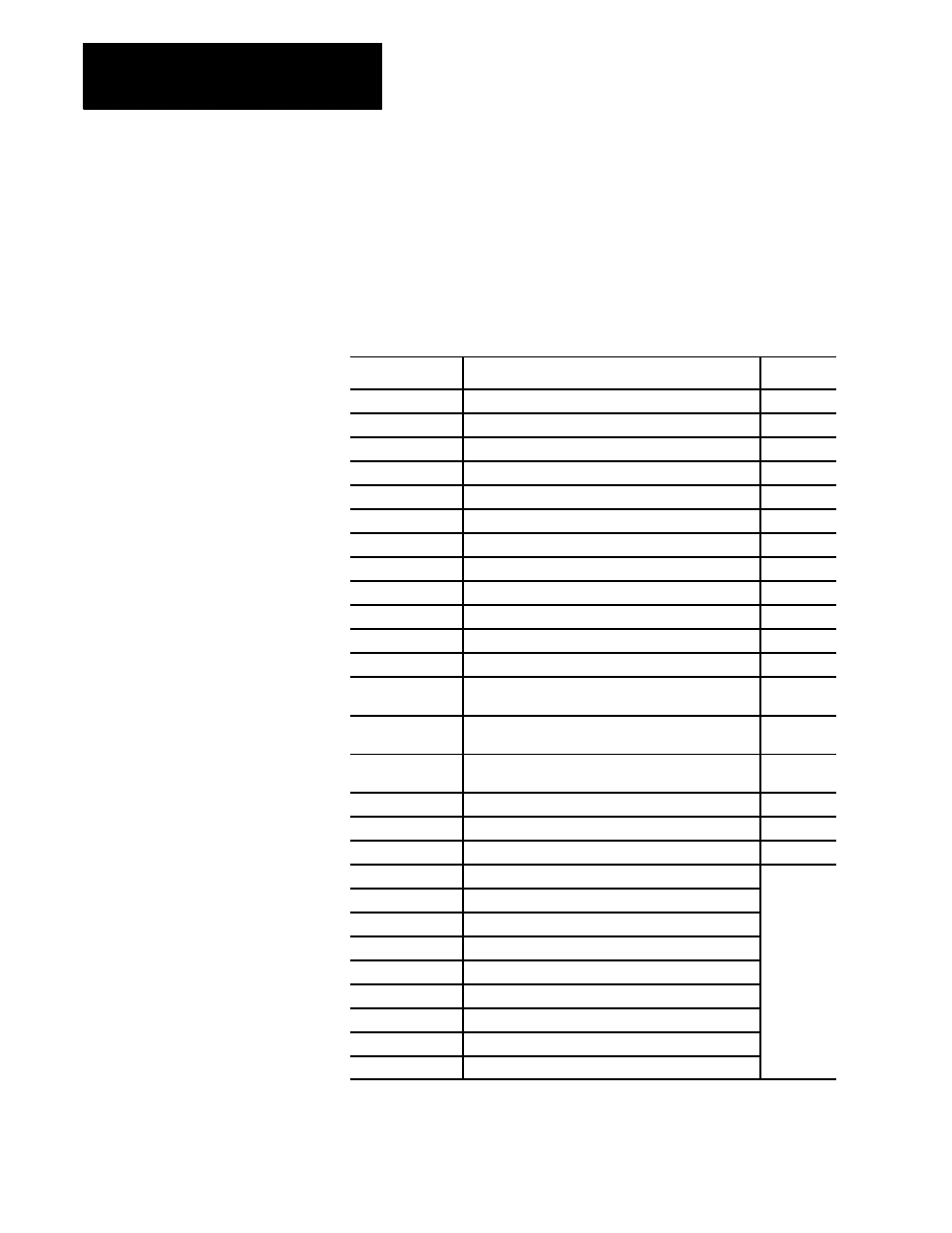
You can use system parameters in any part program, including paramacros
and subprograms. All of these parameters can be used as data or can be
changed by assignment (read and write) unless indicated differently in
Table 20.D. System parameters are generated by the control and can be
modified by operation or programming.
Table 20.D
System Parameters
Parameter #
System Parameter
Page
2001 to 2732
Dresser/Wheel Offset Tables
20-18
3000
2
Program Stop With Message (PAL)
20-18
3001
System Timer (PAL)
20-19
3002
System Clock
20-19
3003
2
Block Execution Control 1
20-19
3004
2
Block Execution Control 2
20-20
3006
2
Program Stop With Message
20-21
3007
1
Mirror Image
20-22
4001 to 4120
1
Modal Information
20-22
5001 to 5012
1
Coordinates of End Point
20-23
5021 to 5032
1
Coordinates of Commanded Position
20-24
5041 to 5052
1
Machine Coordinate Position
20-24
5061 to 5069 or
5541 to 5552
1
Skip Signal Position (Work Coordinate)
20-25
5071 to 5079 or
5561 to 5572
1
Skip Signal Position (Machine Coordinates)
20-26
5081 to 5089 or
5581 to 5592
1
Active Tool Length Offsets
20-27
5095 to 5096
1
Probe Length and Radius
20-28
5101 to 5112
1
Current Following Error
20-29
5201 to 5212
External Offset amount
20-29
5221 to 5232
G54 Work Coordinate Table Value
20-30
5241 to 5252
G55 Work Coordinate Table Value
5261 to 5272
G56 Work Coordinate Table Value
5281 to 5292
G57 Work Coordinate Table Value
5301 to 5312
G58 Work Coordinate Table Value
5321 to 5332
G59 Work Coordinate Table Value
5341 to 5352
G59.1 Work Coordinate Table Value
5361 to 5372
G59.2 Work Coordinate Table Value
5381 to 5392
G59.3 Work Coordinate Table Value
20.3.3
System Parameters