Rockwell Automation 8520-GUM 9/Series CNC Grinder Operation and Programming Manual Documentation Set User Manual
Page 332
Coordinate Control
Chapter 11
11-16
Example 11.6 shows the effect of changing work coordinate systems while
the G92 offset is active:
Example 11.6
Changing Work Coordinate Systems With Offset Active
Program
Comment
N1 G10L2P1X0Z0;
Define G54 work coordinate system zero point to be positioned
X0, Z0 away from the machine coordinate system
N2 G10L2P2X20.Z25.;
Define G55 work coordinate system zero point to be positioned
X20, Z25 away from the machine coordinate system
N3 G55X10.Z5.;
Move to X10, Z5 in the G55 work coordinate system
N4 G54X10.Z5.;
Move to X10, Z5 in the G54 work coordinate system
N5 G92X-5.Z-5.;
Offset current wheel position to be at X-5, Z-5
N6 X15.Z0.;
Move to X15, Z0 (offset still active)
N7 G55X10.Z5.;
Move back to X10, Z5 in the G55 work coordinate system with the
G92 offset still active
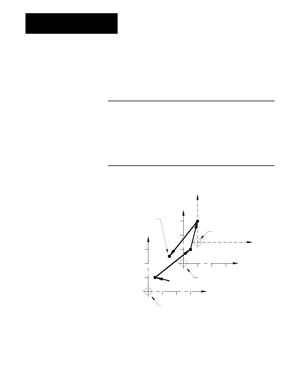
Figure 11.11
Results of Example 11.6
Zero point for the G54
work coordinate system
N3
Zero point for the G55
work coordinate system
New zero point established
by the G92 block
N6
N7
Final move to X10, Z5
after G92 offset was
activated in previous
work coordinate system
N4
X
X
X
Z
Z
Z
10
20
30
10
20
30
30
30
20
10
12177-I
In Example 11.6, the G92 offset, entered while the G54 work coordinate
system was active, has also shifted the G55 coordinate system. Any offsets
described in this section alter all of the work coordinate systems (G54 -
G59) at the same time.