Rockwell Automation 8520-GUM 9/Series CNC Grinder Operation and Programming Manual Documentation Set User Manual
Page 493
Dresser/Wheel Radius Compensation
Chapter 15
15-5
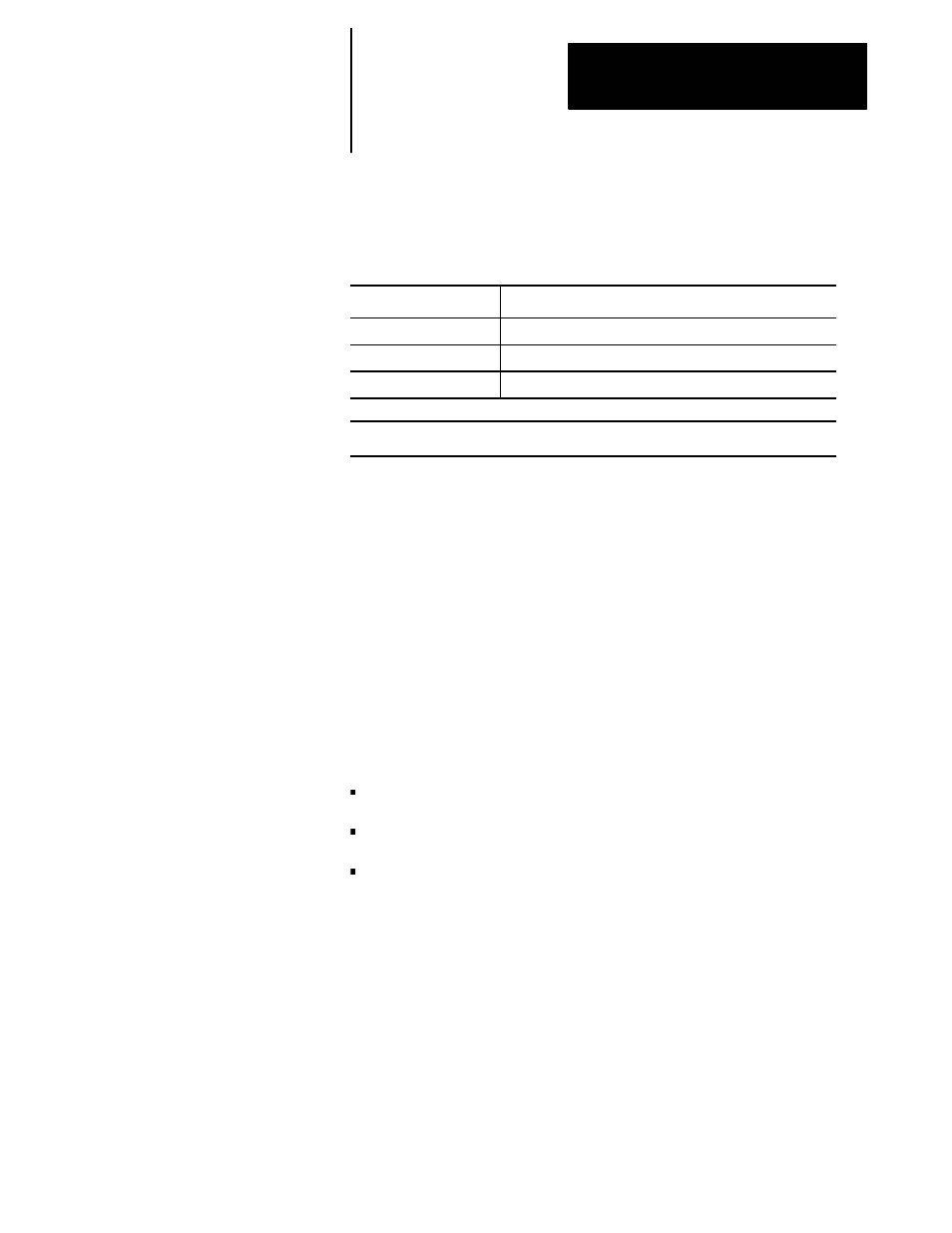
Use the G-codes in Table 15.A for dresser/wheel radius compensation:
Table 15.A
G Code Compensation Direction
G Code
1
:
Dresser/Wheel Radius Compensation:
G40
cancel
G41
left of program path
2
G42
right of program path
2
1
All of these G-codes are modal and belong to the same modal group
2
Left or right is defined as offsetting the dresser/wheel to the left or right of the programmed path
when
facing the direction of axis motion
Important: The dresser/wheel radius compensation function is not
available during thread cutting (G33 and G34). You must cancel
dresser/wheel radius compensation before you perform threading.
Important: If a negative value is set in the offset tables as the
dresser/wheel radius, compensation direction (dresser/wheel left or right) is
reversed for the G41 and G42 codes. You can also reverse G41 and G42
during the mirroring operation. See page 12-79 for details on Mirror
Image operation.
The control supports 3 typical dresser/wheel radius compensation
application schemes. Other schemes can be supported as variations of
these 3 basic applications:
Dresser radius compensation
Corner radius compensation
Entire wheel radius compensation
All of these schemes use the same radius table to store radius values. The
dresser/wheel radius compensation scheme used on your system depends
on the current application of your grinder.
15.2
Programming
Compensation (G40, G41,
G42)
15.2.1
Application Schemes