Block move and chained block move instructions, Figure 2.6 – Avago Technologies LSI8751D User Manual
Page 59
PCI Cache Mode
2-35
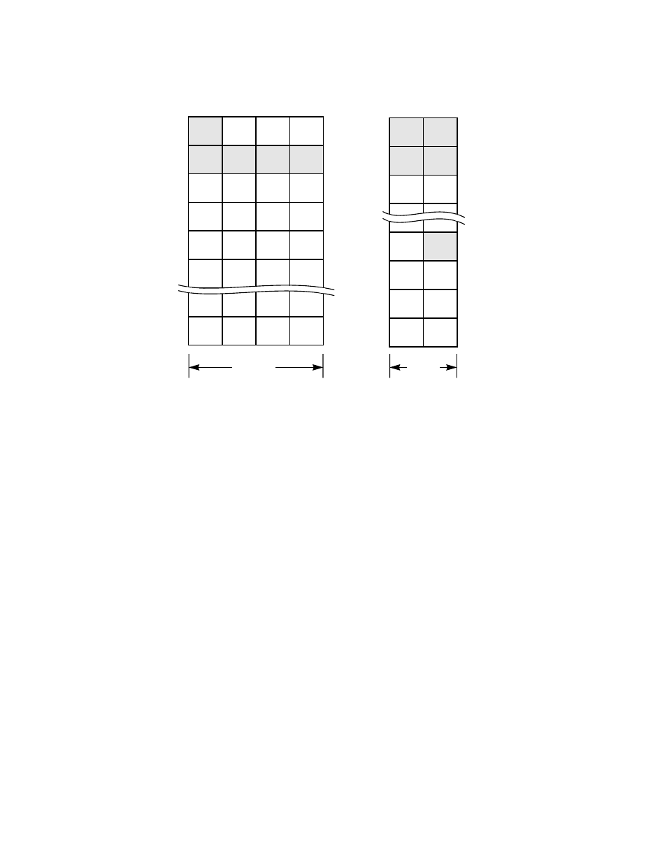
Figure 2.6
Block Move and Chained Block Move Instructions
CHMOV 5, 3 when Data_Out
Moves five bytes from address 0x03 in the host memory to the SCSI bus.
Bytes 0x03, 0x04, 0x05, and 0x06 are moved and byte 0x07 remains in
the low-order byte of the
register and
is combined with the first byte of the following MOVE instruction.
Move 5, 9 when Data_Out
Moves five bytes from address 0x09 in the host memory to the SCSI bus.
2.5.14.1 Wide SCSI Send Bit
The WSS bit is set whenever the SCSI controller is sending data
(Data-Out for initiator or Data-In for target) and the controller detects a
partial transfer at the end of a chained Block Move SCRIPTS instruction
(this flag is not set if a normal Block Move instruction is used). Under this
condition, the SCSI controller does not send the low-order byte of the last
partial memory transfer across the SCSI bus. Instead, the low-order byte
is temporarily stored in the lower byte of the
register and the WSS flag is set. The hardware uses the WSS
flag to determine what behavior must occur at the start of the next data
0x03
0x02
0x01
0x00
0x07
0x06
0x05
0x04
0x0B 0x0A
0x09
0x08
0x0F
0x0E 0x0D 0x0C
0x13
0x12
0x11
0x10
0x04
0x03
0x06
0x05
0x09
0x07
0x0B 0x0A
0x0D 0x0C
32 Bits
16 Bits
Host Memory
SCSI Bus
00
04
08
0C
10