Table 7.12 bidirectional signals—mad[7:0, Bidirectional signals—mad[7:0, Table 7.14 – Avago Technologies LSI8751D User Manual
Page 242
7-6
Instruction Set of the I/O Processor
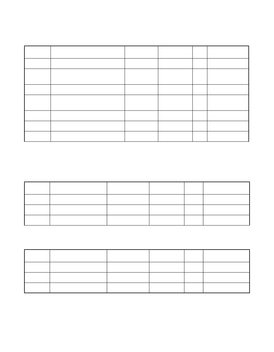
Table 7.12
Bidirectional Signals—MAD[7:0]
Symbol
Parameter
Min
Max
Unit
Test Conditions
V
IH
Input high voltage
2.0
V
DD
+0.5
V
–
V
IH
Input high voltage - external
memory pull-downs
3.85
V
DD
+0.5
V
–
V
IL
Input low voltage
V
SS
−
0.5
0.8
V
–
V
IL
Input low voltage - external
memory pull-downs
V
SS
−
0.5
1.35
V
–
V
OH
Output high voltage
2.4
V
DD
V
−
4 mA
V
OL
Output low voltage
V
SS
0.4
V
4 mA
I
OZ
3-state leakage
−
10
10
µ
A
–
Note: All the signals in this table have 100
µ
A pull-ups that are enabled when TESTIN is low.
Table 7.13
Input Signals—TDI, TMS, TCK (LSI53C875J, LSI53C875JB, LSI53C875N
Only)
Symbol
Parameter
Min
Max
Unit
Test Conditions
V
IH
Input high voltage
3.85
V
DD
+0.5
V
–
V
IL
Input low voltage
V
SS
−
0.5
1.35
V
–
I
IN
Input leakage
−
800
−
200
µ
A
–
Table 7.14
Output Signal—TDO (LSI53C875, LSI53C875JB, LSI53C875N Only)
Symbol
Parameter
Min
Max
Unit
Test Conditions
V
OH
Output high voltage
V
DD
−
0.5
V
DD
V
−
4 mA
V
OL
Output low voltage
V
SS
0.5
V
4 mA
I
OZ
3-state leakage
−
10
10
µ
A
–