Table 2.1 external memory support – Avago Technologies LSI8751D User Manual
Page 31
External Memory Interface
2-7
updates are required, a 7406 (high voltage open collector inverter), an
MTD4P05, and several passive components are also needed. The
memory size and speed is determined by pull-down resistors on the
8-bit bidirectional memory bus at power-up. The LSI53C875 senses this
bus shortly after the release of the Reset signal and configures the ROM
Base Address register and the memory cycle state machines for the
appropriate conditions.
The external memory interface works with a variety of ROM sizes and
speeds. An example set of interface drawings is in
Memory Interface Diagram Examples.”
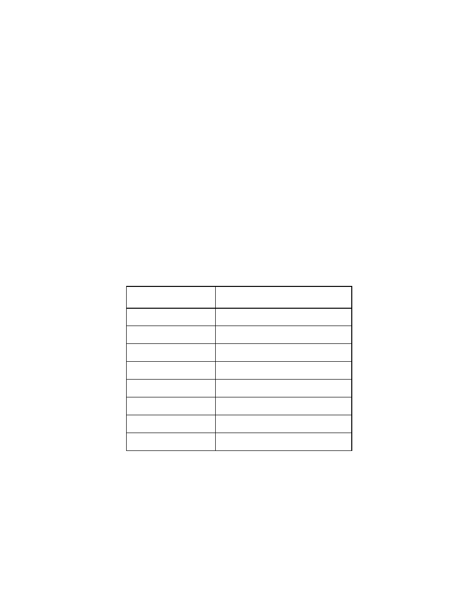
The LSI53C875 supports a variety of sizes and speeds of expansion
ROM, using pull-down resistors on the MAD[3:0] pins. The encoding of
pins MAD[3:1] allows the user to define how much external memory is
available to the LSI53C875.
shows the memory space
associated with the possible values of MAD[3:1]. The MAD[3:1] pins are
fully defined in
Chapter 4, “Signal Descriptions.”
To use one of the configurations mentioned above in a host adapter
board design, put 4.7 k
Ω
pull-down resistors on the MAD pins
corresponding to the available memory space. For example, to connect
to a 32 Kbytes external ROM, use pull-downs on MAD[3] and MAD[2]. If
the external memory interface is not used, then no external resistors are
Table 2.1
External Memory Support
MAD[3:1]
Available Memory Space
000
16 Kbytes
001
32 Kbytes
010
64 Kbytes
011
128 Kbytes
100
256 Kbytes
101
512 Kbytes
110
1024 Kbytes
111
No external memory present