Dma fifo, Dfifo), Dma fifo (dfifo) – Avago Technologies LSI8751D User Manual
Page 155
5-39
Register: 0x20 (0xA0)
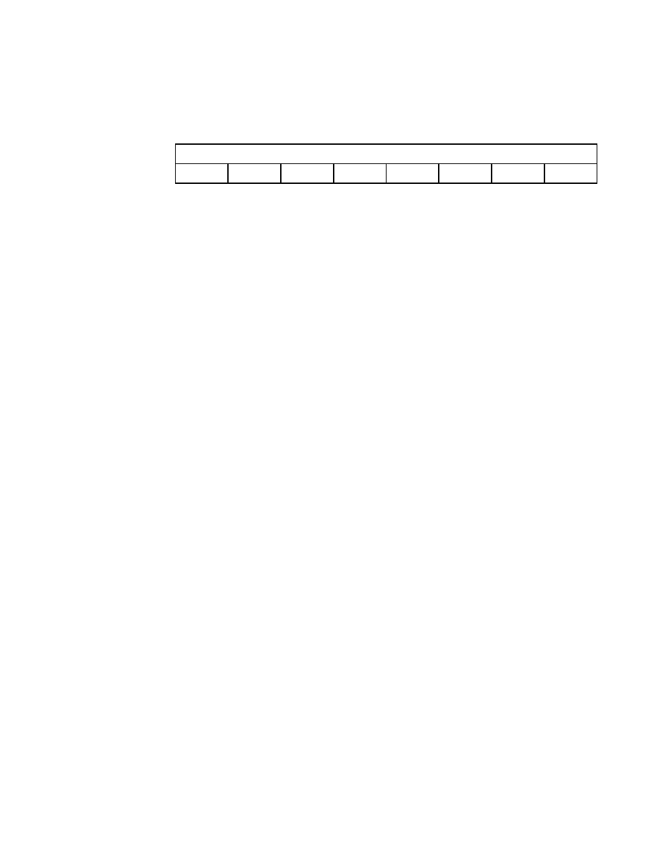
DMA FIFO (DFIFO)
Read/Write
BO[7:0]
Byte Offset Counter
[7:0]
These bits, along with bits [1:0] in the
register, indicate the amount of data
transferred between the SCSI core and the DMA core. It
is used to determine the number of bytes in the DMA
FIFO when an interrupt occurs. These bits are unstable
while data is being transferred between the two cores.
Once the chip has stopped transferring data, these bits
are stable.
The
register counts the number of
bytes transferred between the DMA core and the SCSI
core. The
register counts the
number of bytes transferred across the host bus. The
difference between these two counters represents the
number of bytes remaining in the DMA FIFO.
The following steps determine how many bytes are left in
the DMA FIFO when an error occurs, regardless of the
transfer direction:
If the DMA FIFO size is set to 88 bytes:
1.
Subtract the seven least significant bits of the
register from the 7-bit value of
the
register.
2.
If the DMA FIFO size is set to 536 bytes (using bit 5
of the
register), subtract
the 10 least significant bits of the
register from the 10-bit value of the DMA
FIFO Byte Offset Counter, which consists of
bits [1:0] in the
register
and bits [7:0] of the
register.
7
0
BO
x
0
0
0
0
0
0
0