Avago Technologies LSI8751D User Manual
Page 115
MAD Bus Programming
4-23
•
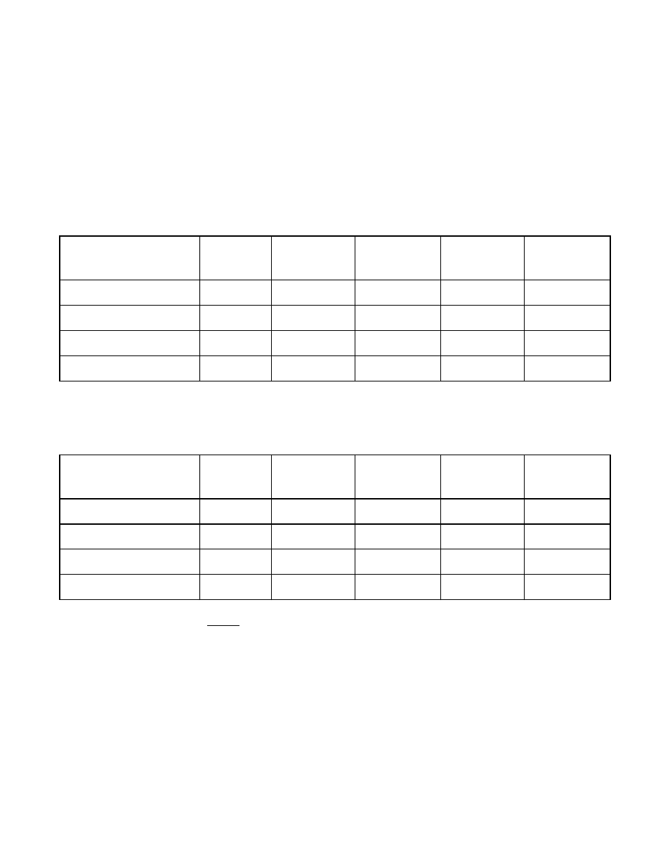
MAD[6] Subsystem Data configuration. Refer to
and
for the different configurations.
•
MAD[5] SCRIPTS RAM disable. Connecting a 4.7 k
Ω
resistor
between MAD[5] and Vss disables SCRIPTS RAM.
•
MAD[4] Subsystem Data configuration. Refer to
and
for the different configurations.
Note:
The chip revisions before Revision G of the LSI53C875
(PCI Rev ID 0x04) do not support different Subsystem Data
Configurations. The
and
registers are hard wired to zero values.
•
MAD[3:1] used to set the size of the external expansion ROM device
attached. Encoding for these pins are listed in
.
Table 4.13
Subsystem Data Configuration Table for the LSI53C875E (PCI Rev ID 0x26)
Mode MAD Pins
Offset
Normal
4-hi, 6-hi
Read/Write
4-hi, 6-lo
Reserved
4-low, 6-hi
LSI Logic
4-low, 6-lo
Vendor ID
0x00
0x1000
0x1000
–
0x1000
Device ID
0x02
0x000F
0x000F
–
0x000F
Subsystem Vendor ID
0x2C
0x1000
0x0000
–
0x0000
Subsystem ID
0x2E
0x1000
0x0000
–
0x0000
Table 4.14
Subsystem Data Configuration Table for the LSI53C875 (PCI Rev ID 0x04),
Revision G Only
Mode MAD Pins
Offset
Normal
4-hi, 6-hi
Read/Write
4-hi, 6-lo
Reserved
4-low, 6-hi
LSI Logic
4-low, 6-lo
Vendor ID
0x00
0x1000
0x1000
–
0x1000
Device ID
0x02
0x000F
0x000F
–
0x000F
Subsystem Vendor ID
0x2C
0x1000
0x0000
–
0x0000
Subsystem ID
0x2E
0x1000
0x0000
–
0x0000