Figure6.1 scripts overview, Scripts overview – Avago Technologies LSI8751D User Manual
Page 200
6-4
Instruction Set of the I/O Processor
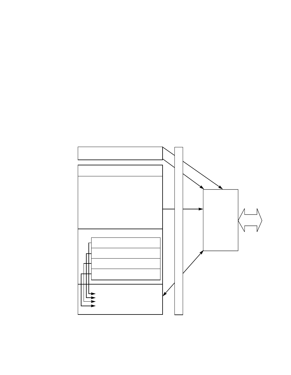
The process repeats until the internally stored byte count has reached
zero. The LSI53C875 releases the PCI bus and then performs another
SCRIPTS instruction fetch cycle, using the incremented stored address
maintained in the
register. Execution of
SCRIPTS instructions continues until an error condition occurs or an
interrupt SCRIPTS instruction is received. At this point, the LSI53C875
interrupts the host CPU and waits for further servicing by the host
system. It can execute independent Block Move instructions specifying
new byte counts and starting locations in main memory. In this manner,
the LSI53C875 performs scatter/gather operations on data without
requiring help from the host program, generating a host interrupt, or
requiring an external DMA controller to be programmed. An overview of
this process is presented in
.
Figure 6.1
SCRIPTS Overview
System Processor
System Memory
SCSI Initiator Write Example
×
Select ATN 0, alt_addr
×
Move from identify_msg_buf, when MSG_OUT
×
Move from cmd_buf, when CMD
×
Move from data_buf when DATA_OUT
×
Move from stat_in_buf, when STATUS
×
Move from msg_in_buf, when MSG_IN
×
Move SCNTL2 & 7F to SCNTL2
×
Clear ACK
×
Wail disconnect alt2
×
Int 10
Table
byte count
address
byte count
address
byte count
address
byte count
address
Message Buffer
Command Buffer
Data Buffer
Status Buffer
S
Y
S
T
E
M
Write DSA
Write
DSP
Fetch
SCRIPTS
Data
LSI53C875
SCSI Bus
B
U
S