Scsi test two, Stest2), Scsi – Avago Technologies LSI8751D User Manual
Page 189: Test two (stest2), Register: 0x4e (0xce)

5-73
2.
Wait 20
µ
s.
3.
Halt the SCSI clock by setting the Halt SCSI Clock bit (
, bit 5).
4.
Set the clock conversion factor using the SCF and CCF fields in the
register.
5.
Set the SCLK Doubler Select bit (
, bit 2).
6.
Clear the Halt SCSI Clock bit.
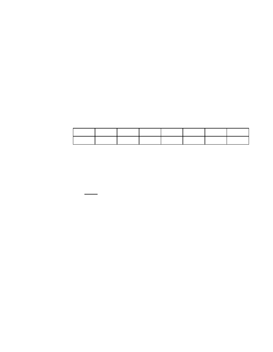
Register: 0x4E (0xCE)
SCSI Test Two (STEST2)
Read/Write
SCE
SCSI Control Enable
7
Setting this bit allows all SCSI control and data lines to
be asserted through the SOCL and
registers regardless of whether the
LSI53C875 is configured as a target or initiator.
Note:
Do not set this bit during normal operation, since it could
cause contention on the SCSI bus. It is included for
diagnostic purposes only.
ROF
Reset SCSI Offset
6
Setting this bit clears any outstanding synchronous
SREQ/SACK offset. Set this bit if a SCSI gross error
condition occurs and to clear the offset when a
synchronous transfer does not complete successfully.
The bit automatically clears itself after resetting the
synchronous offset.
DIF
SCSI Differential Mode
5
Setting this bit allows the LSI53C875 to interface properly
to external differential transceivers. Its only real effect is
to 3-state the SBSY/, SSEL/, and SRST/ pads so that
they can be used as pure inputs. Clearing this bit enables
SE operation. Set this bit in the initialization routine if the
differential pair interface is used.
7
6
5
4
3
2
1
0
SCE
ROF
DIF
SLB
SZM
AWS
EXT
LOW
0
0
0
0
0
0
0
0
