Avago Technologies LSI8751D User Manual
Page 214
6-18
Instruction Set of the I/O Processor
register, and used as an
offset relative to the value in the
register. The
value,
SCSI ID, synchronous offset and synchronous period are
loaded from this address. Prior to the start of an I/O, load
the
with the base address
of the I/O data structure. Any address on a longword
boundary is allowed. After a Table Indirect opcode is
fetched, the
is added to
the 24-bit signed offset value from the opcode to
generate the address of the required data. Both positive
and negative offsets are allowed. A subsequent fetch
from that address brings the data values into the chip.
SCRIPTS can directly execute operating system I/O data
structures, saving time at the beginning of an I/O
operation. The I/O data structure can begin on any
longword boundary and may cross system segment
boundaries. There are two restrictions on the placement
of data in system memory:
•
The I/O data structure must lie within the 8 Mbytes
above or below the base address.
•
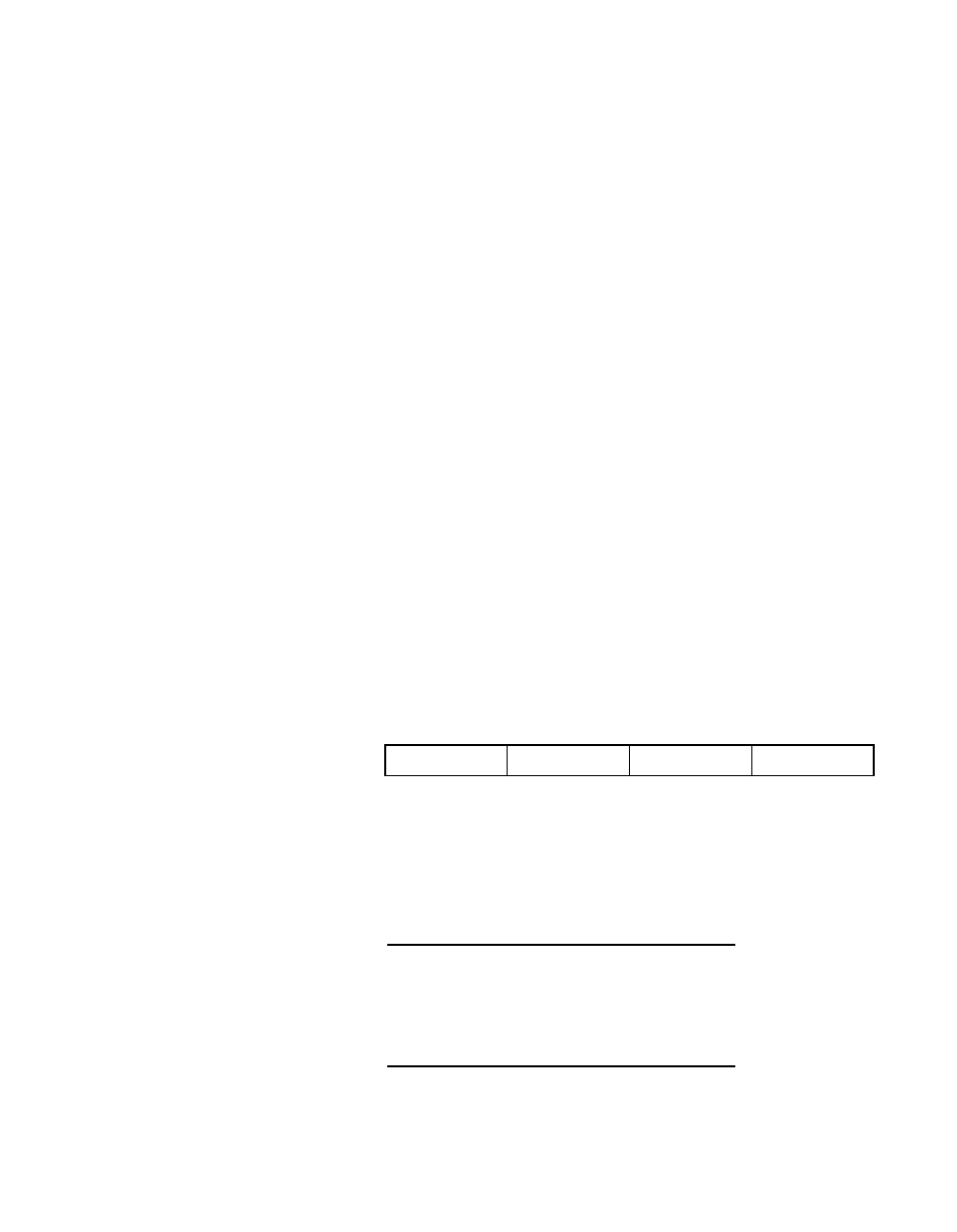
An I/O command structure must have all four bytes
contiguous in system memory, as shown below. The
offset/period bits are ordered as in the
register. The configuration bits are ordered
as in the
register.
Use this bit only in conjunction with the Select, Reselect,
Wait Select, and Wait Reselect instructions. Use bits 25
and 26 individually or in combination to produce the
following conditions:
Config
ID
Offset/period
00
Bit 25
Bit 26
Addressing Mode
0
0
Direct
0
1
Table Indirect
1
0
Relative
1
1
Table Relative