L-force | plc designer – Lenze PLC Designer PLC Designer (R2-x) User Manual
Page 359
L-force | PLC Designer
The Resources
DMS 3.2 EN 02/2011 TD29
357
The module – except for BusMemberID – uses the same input and output
parameters. The parameters STATE and EXTENDEDINFO however have the
following, different meaning:
STATE:INT;
If READY = TRUE then STATE gets one of the following values
which define the actual bus state:
BUSSTATE_BUSOK (Bus is running correctly)
BUSSTATE_BUSFAULT (Bus error)
BUSSTATE_BUSNOTCOMMUNICATING (Communication error)
BUSSTATE_BUSSTOPPED (Bus is stopped)
EXTENDEDINFO:ARRAY[0..129] OF
BYTE;
Manufacturer specific diagnosis data of the bus member; only
the first three bits of the byte are used:
Bit 0: bus member is configured
Bit 1: bus member is active
Bit 2: bus member reports an error, detailled information can
be get via DiagGetState() *)
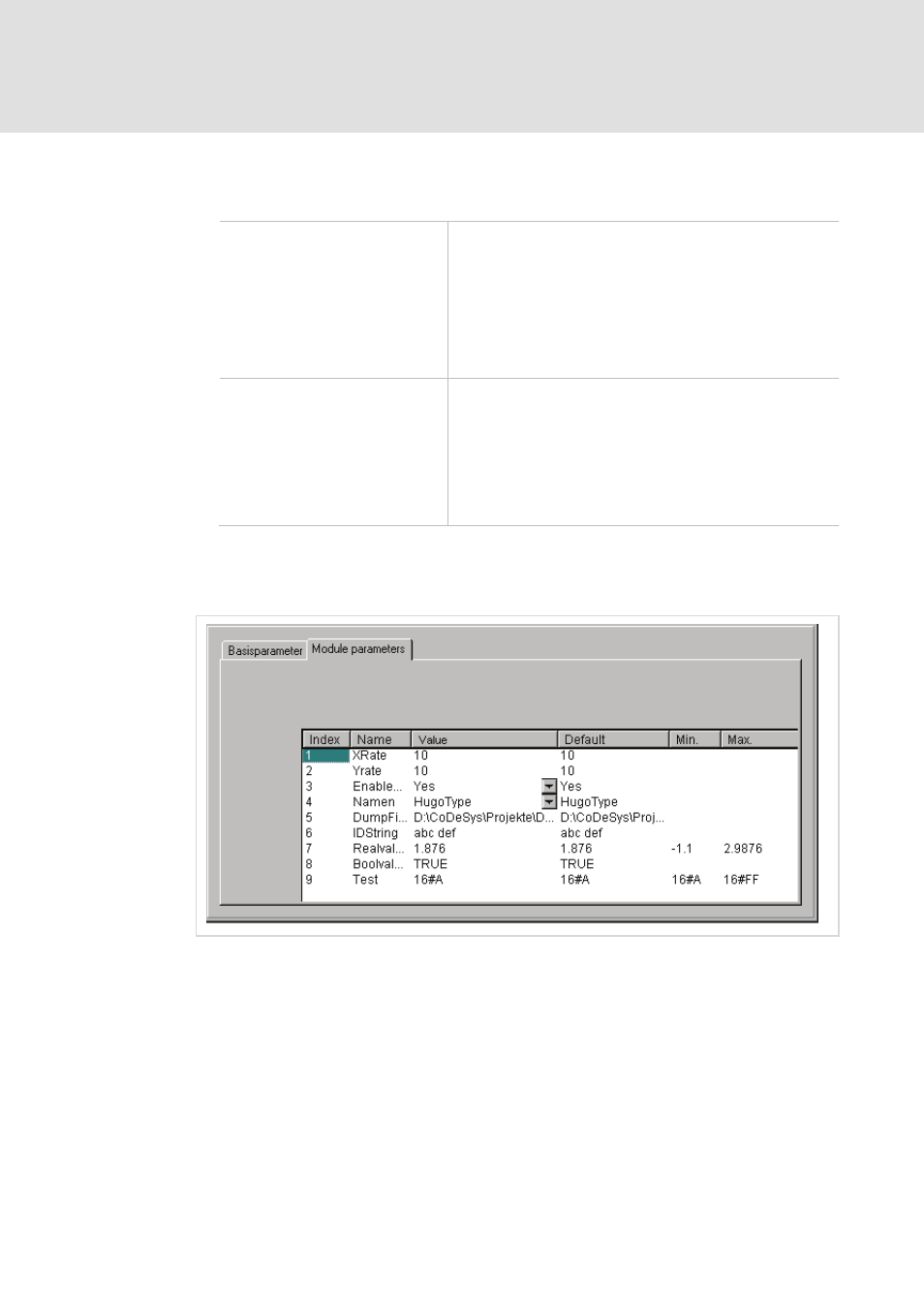
Module parameters / Custom parameters of an I/O Module
Module parameters Dialog
In this dialog the parameters which are given by the device file are shown. Only the
column 'value' is editable.
Index: The Index is a consecutive digit (i), which numbers through all the way the
parameters of the module.
Name: Name of the parameter