The sequential function chart editor, L-force | plc designer – Lenze PLC Designer PLC Designer (R2-x) User Manual
Page 315
L-force | PLC Designer
Editors in PLC Designer
DMS 3.2 EN 02/2011 TD29
313
The Ladder Diagram in the Online Mode
In Online mode, the contacts and coils in the Ladder Diagram that are in the "On" state
are colored blue. Likewise, all lines over which the "On" is carried are also colored blue.
At the inputs and outputs of function blocks, the values of the corresponding variables
are indicated.
Breakpoints can only be set on networks; by using stepping, you can jump from
network to network.
If you place the mouse pointer briefly above a variable, then the type, the address and
the comment about the variable will be displayed in a Tooltip.
7.5.9
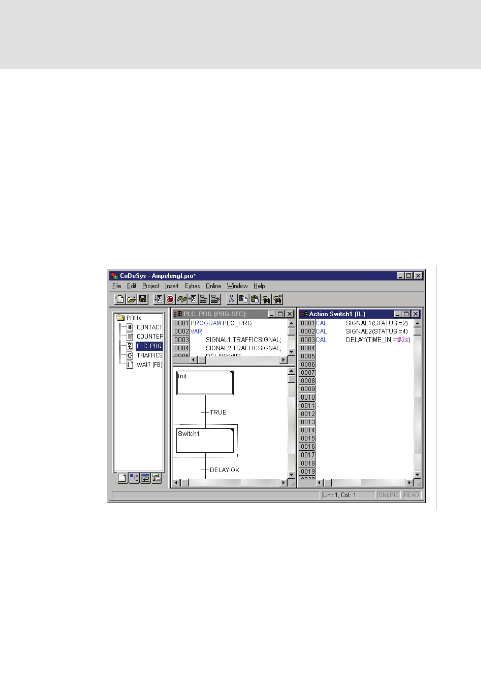
The Sequential Function Chart Editor...
This is how a POU written in the SFC appears in the PLC Designer editor:
All editors for POUs consist of a declaration part and a body. These are separated by a
screen divider.
The Sequential Function Chart editor is a graphic editor. The most important
commands are found in the context menu (right mouse button or
Tooltips show in Offline as well as in Online mode and in the zoomed state the full
names or expressions of steps, transitions, jumps, jump labels, qualifiers or associated
actions.