Table 15. show system environment command – Allied Telesis AT-DC2552XS User Manual
Page 123
AT-DC2552SX Switch Command Line Interface User’s Guide
123
The fields are described in Table 15.
Example
This example displays information about the switch, PSUs, and fan
modules:
awplus# show system environment
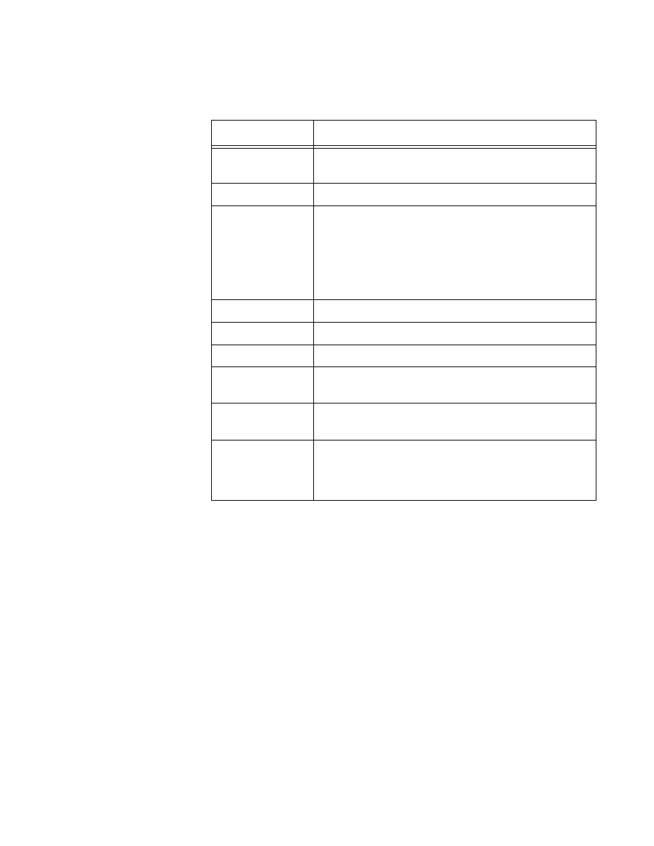
Table 15. SHOW SYSTEM ENVIRONMENT Command
Field
Description
Overall Status
Indicates the status of the unit. The status is either
“Normal” or “***Fault***.”
Resource ID
Indicates the ID of the module.
Name
Indicates the name of the module. The module
names are:
AT-DC2552XS- Indicates the switch.
AT-PWR06 - Indicates the power supply unit.
FAN Tray 01 or 02 - Indicates a fan module.
ID
Indicates the ID of the sensor.
Sensor (Units)
Indicates the name of the sensor.
Reading
Shows the value that the sensor detected.
Low Limit
Displays the specified maximum temperature.
When no value is set, “-” is displayed.
High Limit
Displays the specified minimum temperature. When
no value is set, “-” is displayed.
Status
Indicates the status of the sensor. The options are:
Ok
fault
- AT-GS908M (54 pages)
- AT-x230-10GP (80 pages)
- AT-GS950/48PS (64 pages)
- AT-GS950/10PS (386 pages)
- AT-GS950/16PS (386 pages)
- AT-GS950/48PS (386 pages)
- AT-9000 Series (258 pages)
- AT-9000 Series (1480 pages)
- IE200 Series (70 pages)
- AT-GS950/48 (410 pages)
- AT-GS950/8 (52 pages)
- AT-GS950/48 (378 pages)
- AT-GS950/48 (60 pages)
- SwitchBlade x8106 (322 pages)
- SwitchBlade x8112 (322 pages)
- SwitchBlade x8106 (240 pages)
- SwitchBlade x8112 (240 pages)
- AT-TQ Series (172 pages)
- AlliedWare Plus Operating System Version 5.4.4C (x310-26FT,x310-26FP,x310-50FT,x310-50FP) (2220 pages)
- FS970M Series (106 pages)
- 8100L Series (116 pages)
- 8100S Series (140 pages)
- x310 Series (116 pages)
- x310 Series (120 pages)
- AT-GS950/24 (404 pages)
- AT-GS950/24 (366 pages)
- AT-GS950/16 (44 pages)
- AT-GS950/16 (404 pages)
- AT-GS950/16 (364 pages)
- AT-GS950/8 (404 pages)
- AT-GS950/8 (364 pages)
- AT-GS950/8 (52 pages)
- AT-8100 Series (1962 pages)
- AT-8100 Series (330 pages)
- AT-FS970M Series (330 pages)
- AT-FS970M Series (1938 pages)
- SwitchBlade x3106 (288 pages)
- SwitchBlade x3112 (294 pages)
- SwitchBlade x3106 (260 pages)
- SwitchBlade x3112 (222 pages)
- AT-S95 CLI (AT-8000GS Series) (397 pages)
- AT-S94 CLI (AT-8000S Series) (402 pages)
- AT-IMC1000T/SFP (23 pages)
- AT-IMC1000TP/SFP (24 pages)
- AT-SBx3106WMB (44 pages)