Table 14. show system command – Allied Telesis AT-DC2552XS User Manual
Page 120
Chapter 4: Basic Switch Operations Commands
120
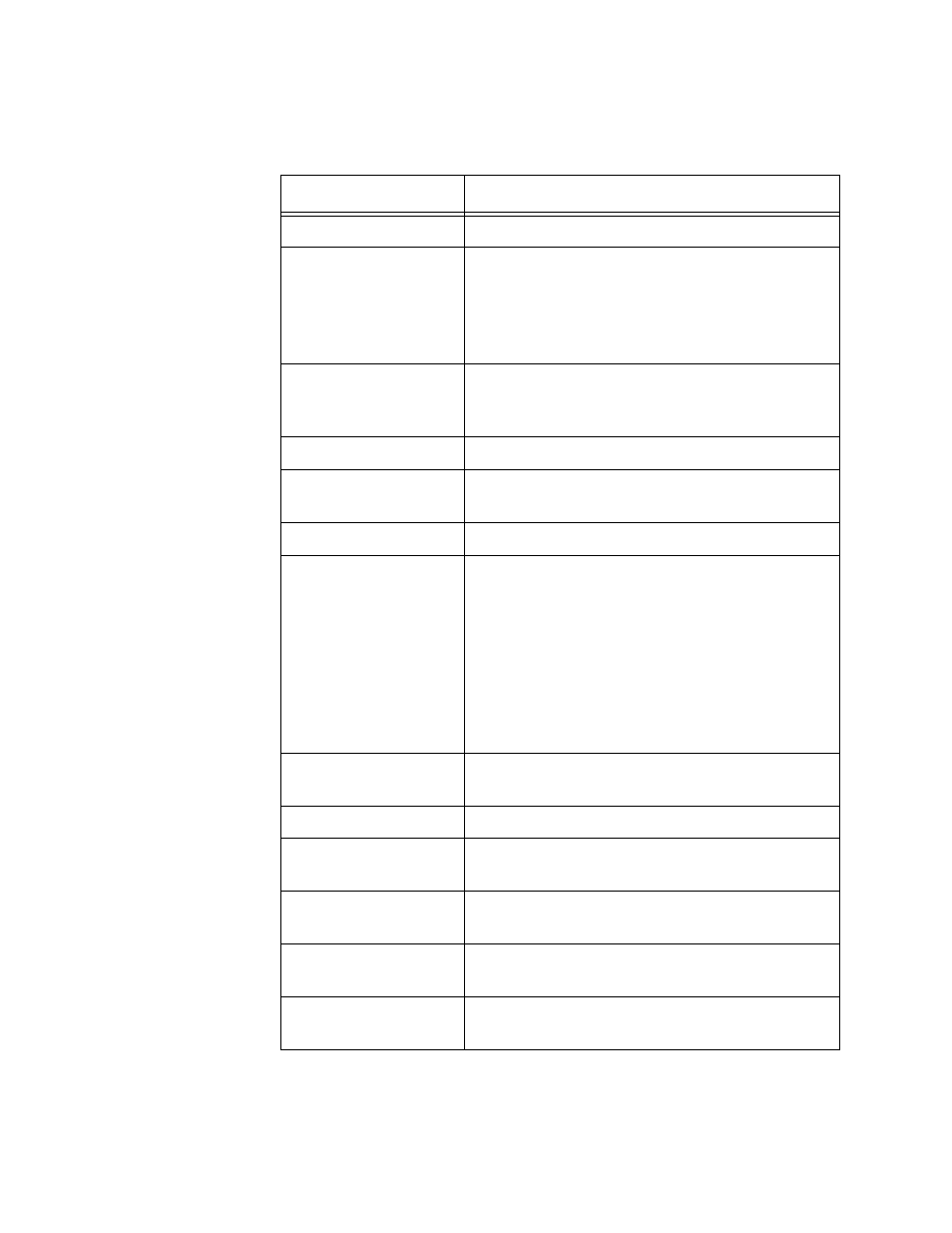
The fields are described in Table 14.
Table 14. SHOW SYSTEM Command
Field
Description
Date and time
Indicates the setting of the system clock.
Board
Indicates a component. The components are:
Base- Indicates the switch.
PSU - Indicates the Power supply unit.
Fan module - Indicates the fan module.
Bay
Indicates a slot number for the board
(component). The base (switch) does not have
a slot number.
Board Name
Indicates the name of the board.
Revision
Indicates the hardware revision number of the
board.
Serial Number
Indicates the serial number of the board.
Environment Status
Indicates the status of the switch. The options
are:
Normal
“***Fault***
To view more detailed information, use the
SHOW SYSTEM ENVIRONMENT command.
See “SHOW SYSTEM ENVIRONMENT” on
page 122.
Uptime
Indicates the length of time since the switch
was last reset or power cycled.
Bootloader version
Indicates the version of the bootloader.
Bootloader build date
Indicates the date and time the bootloader was
built.
Current software
Indicates the file name of the current
management software.
Software version
Indicates the version number of the current
management software.
Build date
Indicates the date and time the current
management software was built.