2 setting items for positioning parameters, Melsec-q – MITSUBISHI ELECTRIC Mitsubishi Programmable Logic Controller QD75D User Manual
Page 92
5 - 4
MELSEC-Q
5 DATA USED FOR POSITIONING CONTROL
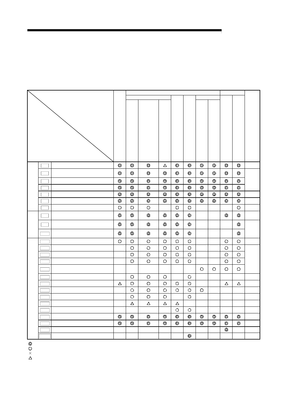
5.1.2 Setting items for positioning parameters
The table below lists items set to the positioning parameters. Setting of positioning
parameters is similarly done for individual axes for all controls achieved by the QD75.
For details of controls, refer to Section 2. For details of setting items, refer to Section
5.2 "List of parameters".
Control
Major positioning control
Manual control
Position control
Other control
Positioning parameter
OP
R co
nt
ro
l
1
-ax
is
l
in
ear
con
tr
o
l
2/
3/
4-
a
x
is
l
ine
a
r i
n
te
rp
ol
a
ti
o
n
co
nt
ro
l
1
-ax
is
f
ix
ed-
fe
ed
c
o
n
tr
o
l
2/
3/
4-
a
x
is
fi
xe
d
-f
e
e
d
co
nt
rol
2-
a
x
is
ci
rc
ul
ar
i
n
te
rpol
ati
o
n c
o
nt
rol
1
to
4 a
x
is
s
p
ee
d co
nt
ro
l
S
p
eed
-p
os
it
io
n
o
r po
s
it
ion
-s
pee
d
co
nt
ro
l
C
u
rr
e
n
t
va
lu
e c
h
an
gi
ng
JU
M
P
i
n
st
ru
cti
o
n,
NOP
in
st
ru
cti
o
n
,
LO
OP
to
LE
N
D
Ma
n
ual
p
u
ls
e g
e
n
e
ra
to
r op
er
at
io
n
J
O
G ope
ra
ti
on
In
ch
in
g op
era
ti
o
n
R
e
la
te
d
s
u
b
f
unc
ti
on
Pr.1
Unit setting
–
Pr.2
No. of pulses per rotation (Ap)
(Unit: pulse)
Pr.3
Movement amount per rotation (Al)
Pr.4
Unit magnification (Am)
12.3.2
Pr.5
Pulse output mode
–
Pr.6
Rotation direction setting
–
B
a
si
c
p
a
ram
et
er
s
1
Pr.7
Bias speed at start
–
–
–
–
–
Pr.8
Speed limit value
–
–
12.4.1
Pr.9
Acceleration time 0
–
–
–
Ba
s
ic
p
a
ra
m
e
te
rs
2
Pr.10
Deceleration time 0
–
–
–
12.7.7
Pr.11
Back compensation amount
–
–
12.3.1
Pr.12
Software stroke limit upper limit value
–
–
–
Pr.13
Software stroke limit lower limit value
–
–
–
Pr.14
Software stroke limit selection
–
–
–
Pr.15
Software stroke limit valid/invalid
selection
–
–
–
–
–
–
12.4.3
Pr.16
Command in-position width
–
–
–
–
–
–
12.7.6
Pr.17
Torque limit setting value
–
–
12.4.2
Pr.18
M code ON signal output timing
–
–
–
–
12.7.3
Pr.19
Speed switching mode
–
–
–
–
–
–
–
Pr.20
Interpolation speed designation method
–
–
–
–
–
–
–
Pr.21
Current feed value during speed control
–
–
–
–
–
–
–
–
–
Pr.22
Input signal logic selection
–
Pr.23
Output signal logic selection
–
Pr.24
Manual pulse generator input selection
–
–
–
–
–
–
–
–
–
–
D
e
ta
iled
p
a
ram
et
ers
1
Pr.150
Speed-position function selection
–
–
–
–
–
–
–
–
–
–
:
Always set
:
Set as required (Read "–" when not required.)
:
Setting not possible
:
Setting restricted
– :
Setting not required. (This is an irrelevant item, so the set value will be ignored. If the value is the default value or within the setting range, there is no
problem.)