Melsec-q, Appendices, Bcd (binary coded decimal) – MITSUBISHI ELECTRIC Mitsubishi Programmable Logic Controller QD75D User Manual
Page 713: Bias speed at start, Bin (binary), Appendix - 71
Appendix - 71
MELSEC-Q
APPENDICES
BCD (Binary Coded Decimal)
1) This is the abbreviation for "binary coded
decimal", more accurately called a BCD
code. Computers, PLCs, etc., use binary
numbers made up of 1 (ON) and 0 (OFF).
Because this is difficult for humans to
understand, decimal digits are expressed
by a pattern of binary digits. Many of the
digital switches and digital displays used by
humans use a BCD code. The significance
of the bits is shown in the drawing below.
Numbers from 0 to 9,999 can be handled
by 16 bits, and numbers from 0 to
99,999,999 can be handled by 32 bits.
0
B15 B14 B13 B12 B11 B10 B9
B8
B7
B6
B5
B4
B3
B2
B1
B0
4000+1000+800+40+20+10+2 = 5.872
5.872
1
0
1
1
0
0
0
0
1
1
1
0
0
1
0
8
000
4
000
2
000
1
000
80
0
400
200
100
80
40
20
10
8
4
2
1
2) BCD commands are commands in which a
binary number (BIN) is converted to a
binary coded decimal (BCD).
They are used to output data from the PLC
and display it on the digital display.
The following drawing shows a 16-bit
example.
0
BIN code
167
0
0
0
0
0
0
0
1
0
1
0
0
1
1
1
0
BCD code
167
0
0
0
0
0
0
1
0
1
1
0
0
1
1
1
P
o
sitiv
e
/
ne
ga
ti
v
e
163
84
8
192
409
6
2
048
1
024
5
1
2
2
5
6
1
2
8
6
4
3
2
1
6
8
4
2
1
800
0
400
0
200
0
100
0
80
0
40
0
20
0
10
0
8
0
4
0
2
0
1
0
8
4
2
1
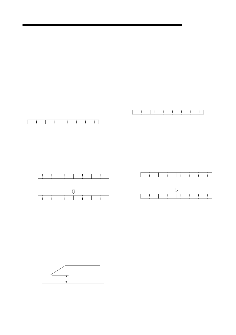
BIAS SPEED AT START
A large amount of torque is required when the
machine starts moving, but the torque may be
unstable at speed 0 with stepping motors.
Therefore, movement can be smoothly carried
out by starting the movement at a given speed
from the beginning. The bias speed at start is
the speed set at that start.
Full speed
Speed 0
Bias speed
BIN (Binary)
1) A binary number, more accurately called a
binary code.
All values are expressed as a binary
number in which 1 turns the PLC, etc.,
electricity ON, and 0 turns it OFF. The
significance of the bits is shown in the
drawing below. In the MELSEC PLC, the
highest order bit (B15) is used to indicate
handling as a positive No. (0), or negative
No. (1), so the 15 bits from B0 to B14 are
valid.
0
B15 B14 B13 B12 B11 B10 B9
B8
B7
B6
B5
B4
B3
B2
B1
B0
128+32+4+2+1=167
167
0
0
0
0
0
0
0
1
0
1
0
0
1
1
1
2
15
2
14
2
13
2
12
2
11
2
10
2
9
2
8
2
7
2
6
2
5
2
4
2
3
2
2
2
1
2
0
Posi
ti
ve/
negati
v
e
16
38
4
=
81
92=
40
96=
20
48=
10
24=
512
=
256
=
128
=
64
=
32
=
16
=
8
=
4
=
2
=
1
=
2) BIN commands are commands in which a
binary coded decimal (BCD) is converted to
a binary number (BIN).
They are used to input the data shown on
the digital switch to the PLC.
The following drawing shows a 16-bit
example.
0
BCD code
167
0
0
0
0
0
0
1
0
1
1
0
0
1
1
1
0
BIN code
167
0
0
0
0
0
0
0
1
0
1
0
0
1
1
1
Posi
tive/
nega
tive
80
00
40
00
20
00
10
00
80
0
40
0
20
0
10
0
80
40
20
10
8
4
2
1
1
638
4
819
2
409
6
204
8
102
4
5
1
2
2
5
6
1
2
8
6
4
3
2
1
6
8
4
2
1