Download mode, 9000 front panel operation – Verilink 9000 Series (34-00271) Product Manual User Manual
Page 60
38
C
HAPTER
3: H
ARDWARE
O
PERATION
Download
Mode
The Download mode enables the unit to receive firmware through the supervisory
port. This is used to download the core operating system to the unit. This mode is
only used to update the core operating system and not firmware options. In most
cases, this is used only by the factory.
For more information regarding the Download mode, see 9101-, 9111-, and
9211-Specific Core Download Procedure on page 77.
9000 Front
Panel
Operation
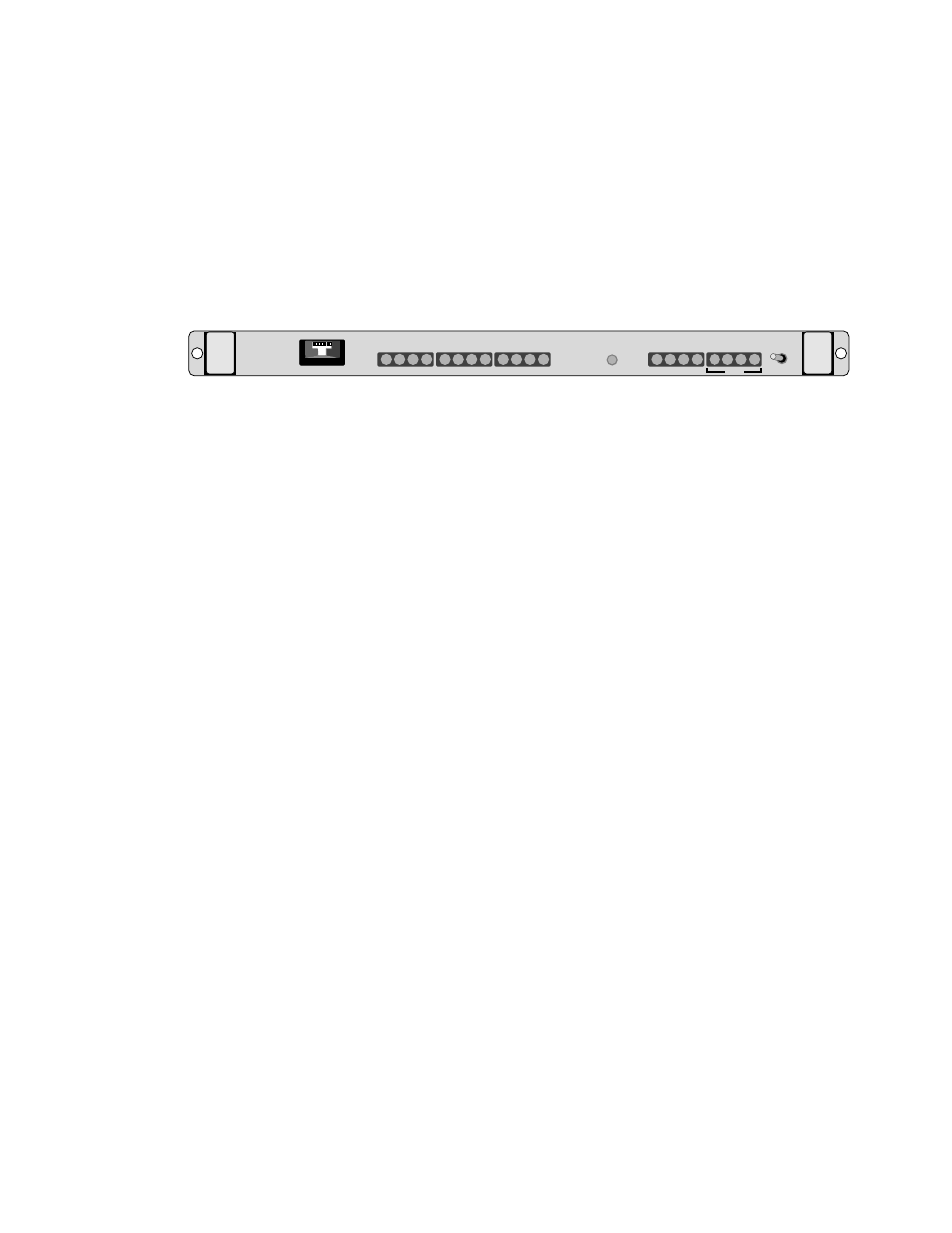
Figure 3-2 shows the 9000 front panel which has three control switches and 20
LED indicators. Table 3-2 references by number these front panel controls and
indicators and provides a brief description.
Run/Config
Switch
This switch is located on the right side of the front panel of each 9000 card. For
normal operation, the Run/Config switch must be in the Run position. Setting the
switch to Config is used for initial installation and forces the communications
platform to operate with a default configuration. This setting should only be used
with assistance from TXPORT Technical Support.
Port
Select
Switch
This switch is located on the left side of the front panel of each 9000 card. The
Port Select Switch is a thumbwheel numbered from 0 to 9. Setting this switch to
any number from 1 to 4 causes the labeled LEDs to show the status of the modem
control and other status signals for the selected port. Settings 0, 7, 8, and 9 are
reserved for special functions such as firmware upgrades, etc. Never leave a unit
set to 0, 7, 8, or 9 as this could cause unpredictable behaviour if power is lost and
then restored. The LED display can be used to help diagnose problems on any port
of the 9000 MultiPro platform card.
Reset
Switch
The reset switch is located on the right side of the front panel, just to the left of
the Run/Config switch. The switch allows resetting an individual line module.
Signal
Indicators
The 9000 MultiPro card has several indicators to assist in confirming proper
operation of the unit and resolving possible problems with the network. These
indicators are located on the front panel of the unit.
RUN
1
MODEL
9000
Port No
TxD
RxD
TxC
RxC
RTS
CTS
DTR
DSR
DCD
DTE
TDI
V35
1 2 3 4
TxD
RxD
FLT
MAC
CONFIG
RESET
LAN
Figure 3-2 MultiPro 9000 Front Panel