Verilink 9000 Series (34-00271) Product Manual User Manual
Page 28
6
C
HAPTER
1: G
ENERAL
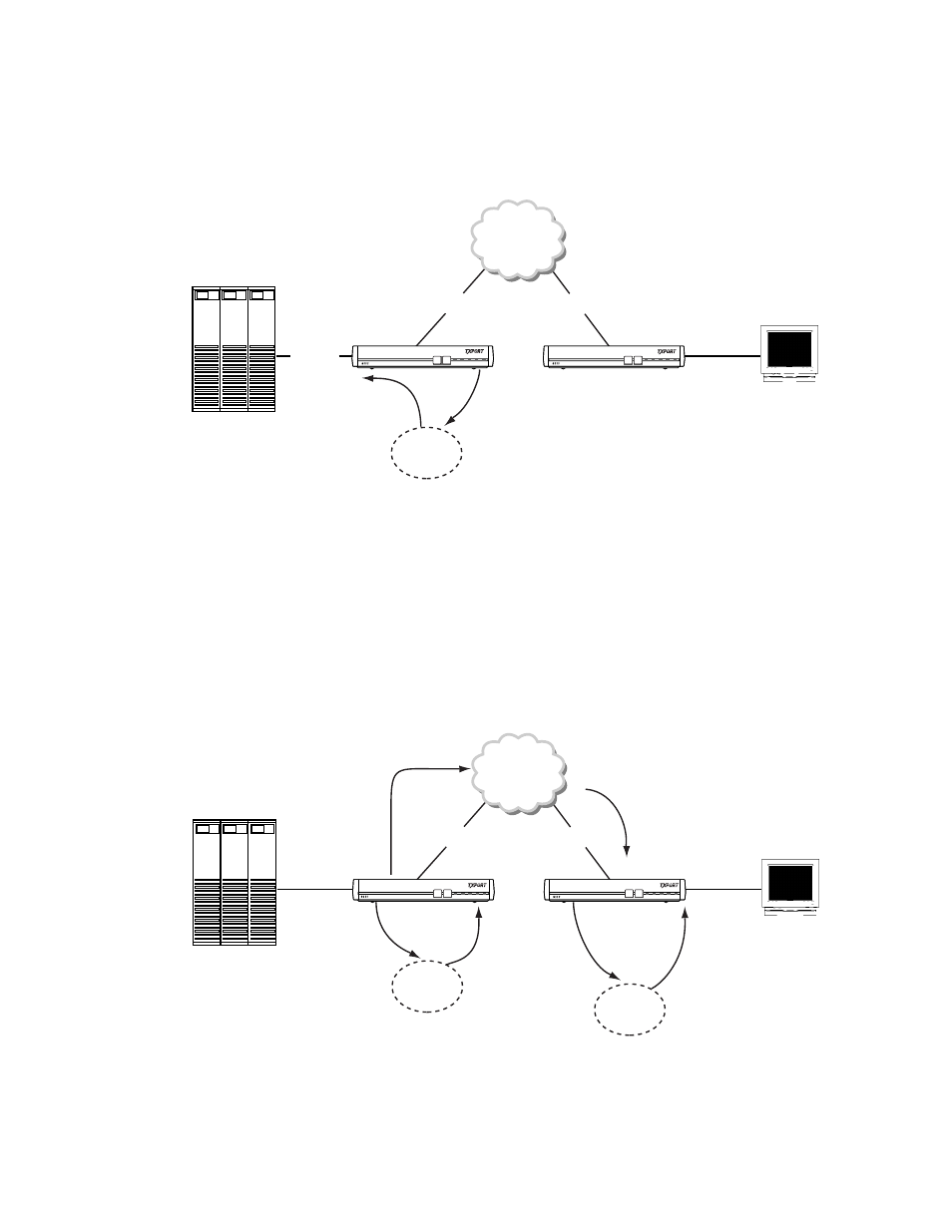
After receiving a call request to HOSTA, Port 1 on unit 001 forwards the request
as a connection request to HOSTA to its own OS. Upon receiving the connection
request to HOSTA, unit 001’s OS finds that HOSTA is defined in Port 3’s HOST
Name field. The connection request to HOSTA is then passed to Port 3 on unit
001, as shown in Figure 1-5.
Unit 001’s Port 3 receives the connection request to HOSTA, and verifies that
HOSTA is defined on the port. A connect confirmation to HOSTA is returned to the
OS, and the connect confirmation to HOSTA traverses to Port 4 on unit 002, the
originator of the connect request to HOSTA, as is shown in Figure 1-6.
After the connect confirmation has traversed to Port 4 of Unit 002, a logical
connection is established. This logical connection is between the terminal on Port
4 of unit 002, whose address is AA, and Port 3 of unit 001, which is connected to
an external host. This logical connection remains until the unit is reset or optioned
to disconnect under specific circumstances.
HOST
HOSTA
DLCI 15
DLCI 16
PORT 1 to OS:
Connection request to HOSTA
OS to PORT 3:
Connection request
to HOSTA
Frame Relay
Terminal
Address = AA
DOWNLOAD CONFIG
MODE BACKUP
NET
ALARM POWER
DOWNLOAD CONFIG
MODE BACKUP
NET
ALARM POWER
UNIT 002
OS
Figure 1-5 Connection Request to HOSTA Passed to Port 3
HOST
DLCI 15
DLCI 16
PORT 3 to OS:
Connect confirmation
to HOSTA
PORT 1 to FRY:
Call accept to
HOSTA
FRY to PORT 1:
Call accept to HOSTA
OS to PORT 3:
Connect confirmation
to HOSTA
Frame Relay
Terminal
Address = AA
DOWNLOAD CONFIG
MODE BACKUP
NET
ALARM POWER
DOWNLOAD CONFIG
MODE BACKUP
NET
ALARM POWER
UNIT 002
OS
PORT 1 to OS:
Connect confirmation
to HOSTA
OS to PORT 4:
Connect confirmation
to HOSTA
OS
Figure 1-6 Connect Request to HOSTA