Changing the interface on port 2, Figure 2-9 – Verilink 9000 Series (34-00271) Product Manual User Manual
Page 51
9111 Connections
29
Changing the Interface on Port 2
CAUTION: The circuit boards are susceptible to damage caused by static electricity.
Use electrostatic device (ESD) precautionary measures, such as wearing static
grounding straps and storing modules in antistatic bags.
1
Disconnect power from the
unit.
2
Remove all connections from
the unit.
3
Place the unit on an
ESD-approved work area.
4
Lay the unit on its top (upside
down) with the front panel
toward you.
5
Remove the four screws in the
base of the unit using a
Phillips-head screwdriver.
6
Lift the unit from underneath
and set it down on its base
with the front panel facing
you.
7
Remove the cover from the
unit.
8
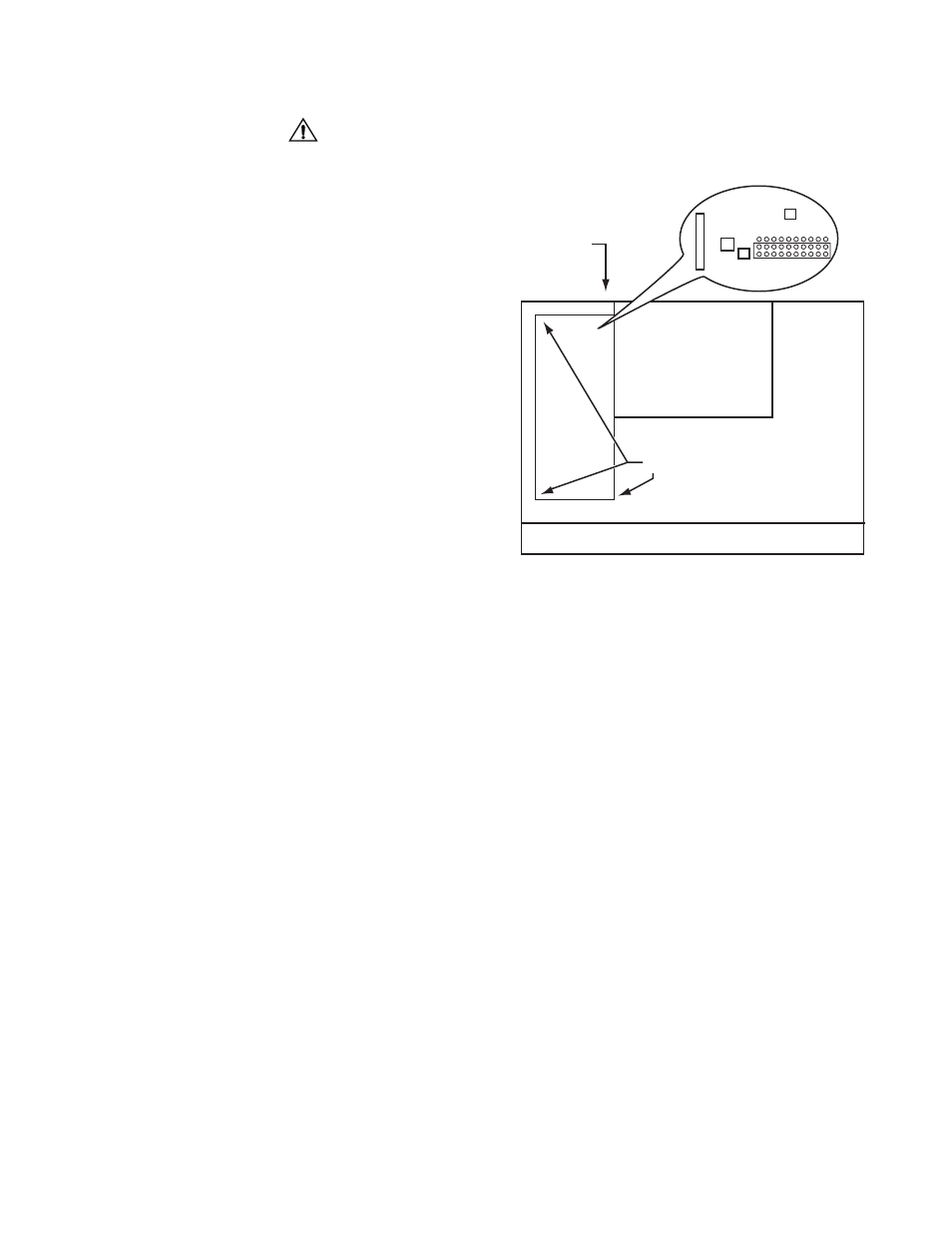
Remove the DDS or T1 card by removing the Phillips-head screw near J8,
pinching the two near white, plastic standoffs (refer to Figure 2-9) and slightly
lifting the DDS or T1 card, pinching the standoff near the connector Port 2, and
lifting the DDS or T1 card.
9
Gently lift and set the RS-232/V.35 jumper located on the motherboard beside J8
to the (refer to Figure 2-9) desired position.
10
Assemble the unit in reverse order, taking special care to properly reconnect J8 and
J12 when attaching the DDS card.
Standoff
PORT 2
Ethernet Card
DDS Card
J12
V .35
RS-232
J8
Front 9111
Figure 2-9 Location of Port 2 RS-232/V.35 Header