Host, Hosta, Unit 002 – Verilink 9000 Series (34-00271) Product Manual User Manual
Page 27: Terminal address = aa, Principles and concepts 5, Dlci 15 dlci 16 frame relay
Principles and Concepts
5
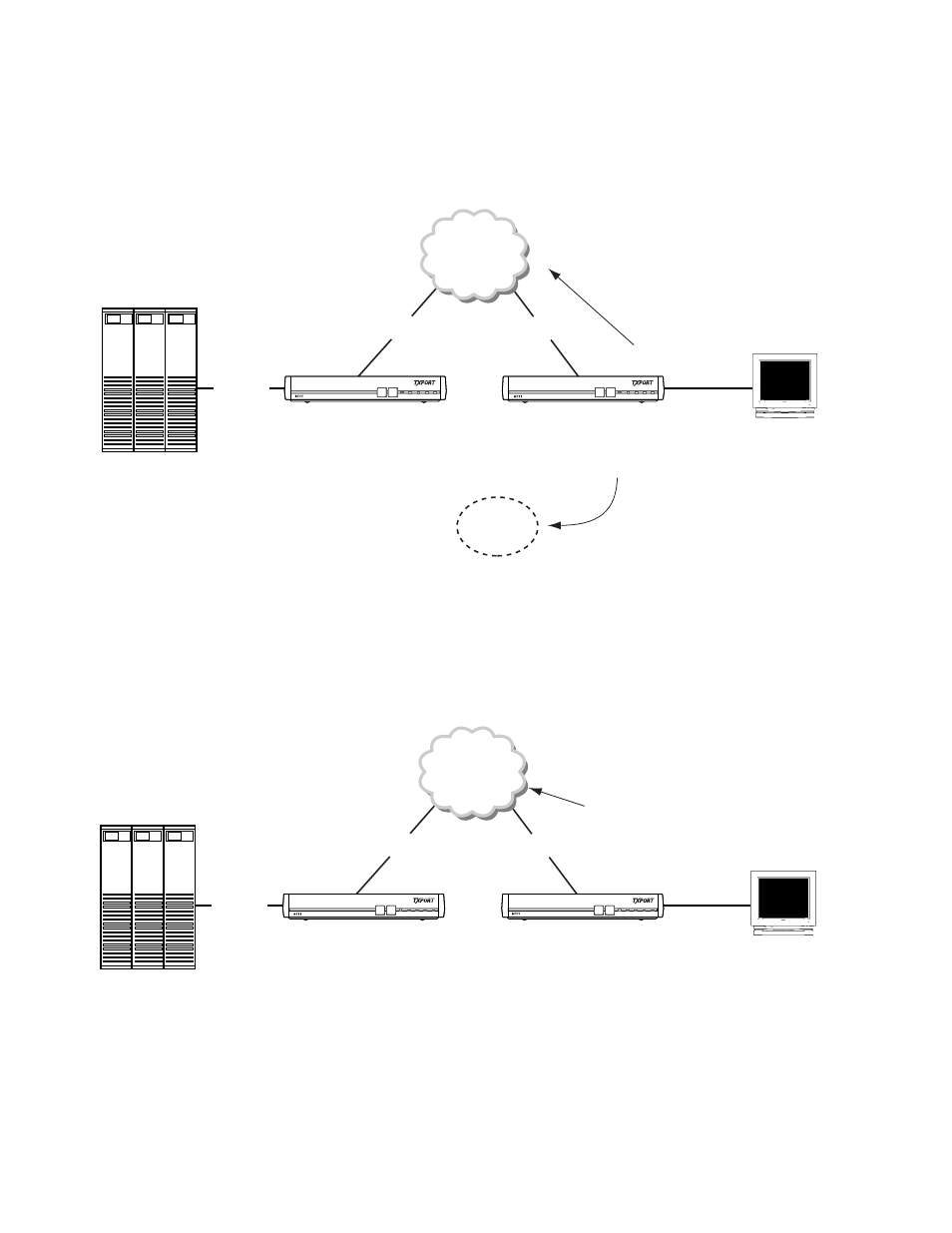
Consider the scenario where both units have recently powered up, or been reset.
Port 4 on Unit 2 polls the first device, terminal AA, in its address list and gets a
response. After receiving this response, Port 4 issues a connect request to HOSTA,
the corresponding connect name for address AA. The connect request to HOSTA is
issued to Unit 002’s Operating System (OS), as shown Figure 1-3.
Unit 002’s OS receives the connection request to HOSTA and finds HOSTA defined
in Port 1’s Endpoint List. The connection request is passed to Port 1. Port 1
receives the connection request to HOSTA from unit 002’s OS, and upon finding
HOSTA in its Endpoint List, transmits a call request to HOSTA out the Frame
Relay connection, over DLCI 16, as shown in Figure 1-4.
Figure 1-3 Connect Request to HOSTA Is Issued to Unit 002’s Operating System
DOWNLOAD CONFIG
MODE BACKUP
NET
ALARM POWER
DOWNLOAD CONFIG
MODE BACKUP
NET
ALARM POWER
HOST
HOSTA
DLCI 15
DLCI 16
Frame Relay
Terminal
Address = AA
PORT 4 to OS
Connection request to HOSTA
OS
UNIT 002
HOST
HOSTA
DLCI 15
DLCI 16
PORT 1 to FRY:
Call request to HOSTA
Frame Relay
Terminal
Address = AA
DOWNLOAD CONFIG
MODE BACKUP
NET
ALARM POWER
DOWNLOAD CONFIG
MODE BACKUP
NET
ALARM POWER
UNIT 002
Figure 1-4 Port 1 Transmits a Call Request to HOSTA