9000 connections, Power console port ethernet, Aui port – Verilink 9000 Series (34-00271) Product Manual User Manual
Page 56
34
C
HAPTER
2: I
NSTALLATION
9000
Connections
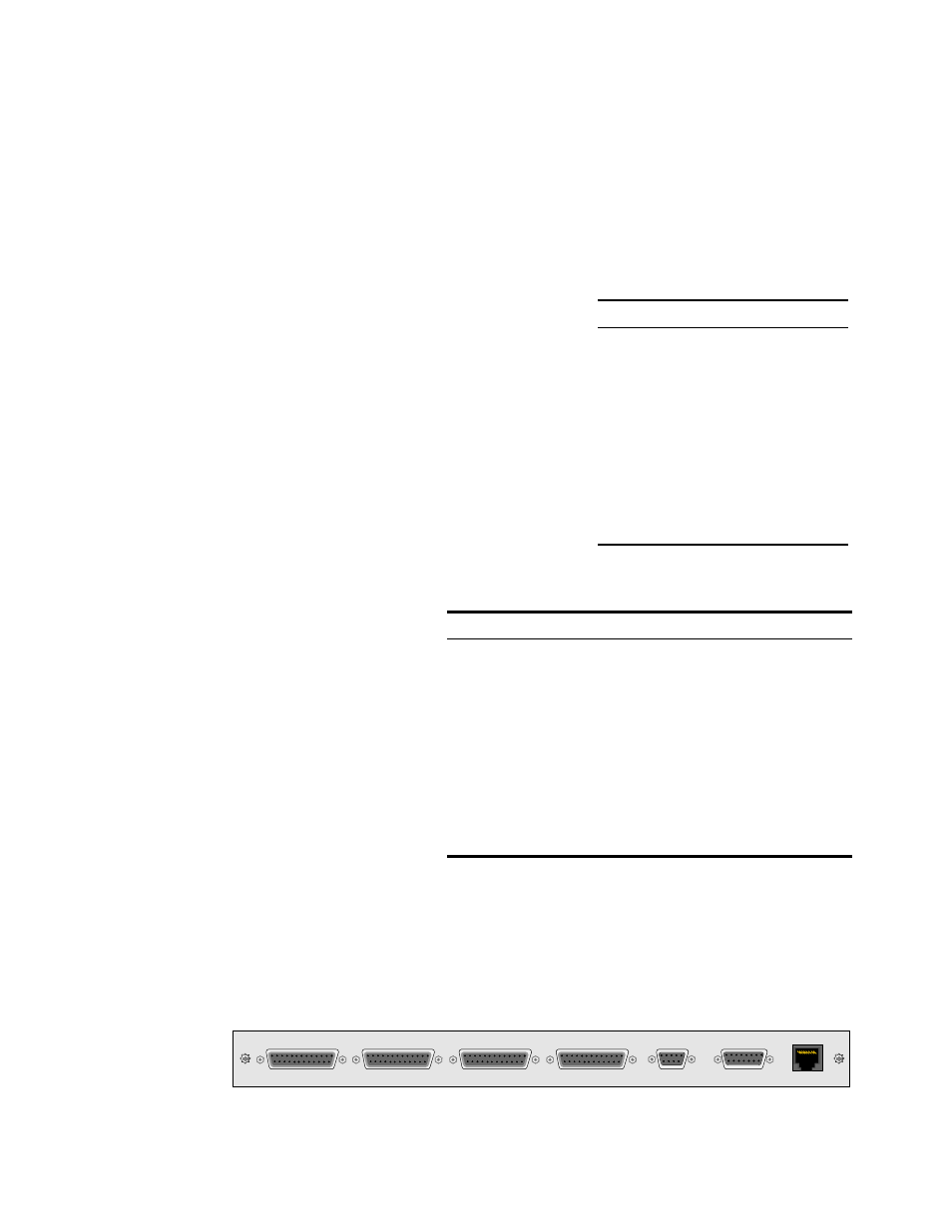
Figure 2-13 shows the rear panels of the 9000, including the power connector;
UTP and AUI Ethernet connectors; supervisory connector; and connectors for ports
1 through 4.
Power
Verify the chassis is not connected to a power source. Insert the 9000 MultiPro
platform card into the chassis. Plug the power cord into an appropriate outlet. This
applies power to the unit.
Console
Port
The Console port allows local, direct
connection of the unit to an ASCII-
character-based terminal or a PC running a
terminal emulation program. The form
factor of the connector is female DB-9.
Table 2-21 shows the pinout.
Ethernet
AUI Port
Table 2-22 shows the
pinout of the AUI
(attachment unit
interface) port. The
form factor of the
connector is female
DB-15.
PORT 1
PORT 2
PORT 3
PORT 4
CONSOLE
AUI
UTP
13
1
14
25
13
1
14
25
13
1
14
25
13
1
14
25
8
8
1
1
9
15
5
9
1
6
Figure 2-13 TXPORT 9000 Rear Panel
Table 2-21 Console Port Pinout
Pins
Signal
1
Carrier Detect (DCD)
2
Received Data (RD)
3
Transmitted Data (TD)
4
Data Terminal Ready (DTR)
5
Signal Ground (SG)
6
Data Set Ready (DSR)
7
Request to Send (RTS)
8
Clrear To Send (CTS)
9
not connected
Table 2-22 AUI Port Pinout
Pin
Circuit
Signal
1, 2, 6, 8, 9, 13, and 14
not used
3
DO-A
Data Out, Circuit A
4
DI-S
Data In, Circuit Shield
5
DI-A
Data In, Circuit A
7
CO-A
Control Out, Circuit A1
10
DO-B
Data Out, Circuit B
11
DO-S
Data Out, Circuit Shield 1
12
DI-B
Data In, Circuit B
15
CO-B
Control Out, Circuit B