9111 port 1 dds option testing, Remote channel loop, Port 2 – Verilink 9000 Series (34-00271) Product Manual User Manual
Page 50
28
C
HAPTER
2: I
NSTALLATION
9111 Port 1
DDS Option
Testing
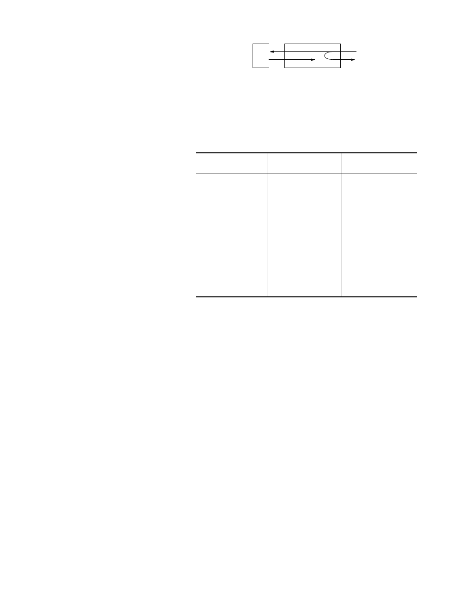
Remote Channel Loop
This loop is activated by
receiving a minimum of four
consecutive bytes of the
non-latching loopback code at
the proper data rate and remains looped as long as every other byte contains the
loopback code and continues for a minimum of four consecutive bytes after
receiving the last loopback code. Figure 2-8 shows the channel loop.
Port 2
Port 2 is a DTE
port. Its
interface is
RS-232 or V.35,
depending on a
jumper on the
main PCB. The
default is V.35.
To change this
jumper, see
Figure 2-9.
Table 2-13
shows the
pinout of Port 2.
DTE
NET
Figure 2-8 Channel Loop
Table 2-13 Port 2 Pinout
Signal
RS-232C
Circuit
Pin
V.35
Circuit
Pins
A/B
Shield Ground
AA
1
FG
1
Transmit Data
BA
2
SD
2/14
Receive Data
BB
3
RD
3/16
Request to Send
CA
4
RTS
4
Clear to Send
CB
5
CTS
5
Data Set Ready
CC
6
DSR
6
Signal Ground
AB
7
SG
7
Data Carrier Detect
CF
8
RLSD
8
Transmit Clock
DB
15
SCT
15/12
Receive Clock
DD
17
SCR
17/9
DTE Ready
CD
20
DTR
20
External Clock
DA
24
SCTE
24/11
- 1061 T1 Multicast (34-00268) Product Manual (18 pages)
- 2010 (34-00204) Product Manual (15 pages)
- 1558A (34-00228) Product Manual (39 pages)
- 1558D (34-00255) Product Manual (42 pages)
- 210 (34-00196) Product Manual (9 pages)
- 2000 (34-00182) Product Manual (58 pages)
- 300 (34-00199) Product Manual (9 pages)
- 2048 (34-00179) Product Manual (33 pages)
- 400 (34-00222) Product Manual (9 pages)
- 2100 (34-00187) Product Manual (19 pages)
- 7200p Series IAD (34-00334.B) Product Manual (311 pages)
- APS 2000 T1 Line Protection (880-502411-001) Product Manual (87 pages)
- AS200 (896-502379-001) Product Manual (112 pages)
- AS420 (34-00294) Product Manual (28 pages)
- AS56/56Plus (896-502588-001) Product Manual (130 pages)
- AS2000: The Basics (880-502981-001) Product Manual (179 pages)
- Access Manager 2000 (896-502037-001) Product Manual (400 pages)
- ConnecT 56K DSU (896-502110-001) Product Manual (88 pages)
- AS4000 (34-00244) Product Manual (210 pages)
- C150 (880-502893-001) Product Manual (135 pages)
- Craft Interface (No Part Number) Product Manual (8 pages)
- DDS Lite (34-00295.C) Product Manual (19 pages)
- DCSU 2911 (880-502647-001) Product Manual (79 pages)
- DIDCSU 2912 (880-502646-001) Product Manual (107 pages)
- DIU 2130 (880-503297-001) Product Manual (101 pages)
- DIU 2131 (880-502765-001) Product Manual (31 pages)
- FrameStart FSE (34-00291.F) Product Manual (49 pages)
- DPRI 2922 (880-503142-001) Product Manual (91 pages)
- HDM 2180 (880-503048-001) Product Manual (79 pages)
- HDM 2182 (880-502925-001) Product Manual (81 pages)
- IMUX (880-503137-001) Product Manual (48 pages)
- FrameStart FSM (34-00299.E) Product Manual (153 pages)
- TAC 2010 (880-503298-001) Product Manual (65 pages)
- M1-3 (880-503136-001) Product Manual (75 pages)
- NCC 2130 (880-503285-001) Product Manual (61 pages)
- NCM 2000 (880-502623-001) Product Manual (91 pages)
- NetPath 2000 Product Manual (30 pages)
- PRISM 3000 (34-00184) Product Manual (45 pages)
- PRISM 3001 (34-00186) Product Manual (58 pages)
- PRISM 3002 (34-00277) Product Manual (52 pages)
- Net Engine (3150-30626-001) Product Manual (323 pages)
- PRISM 3021 (34-00262) Product Manual (47 pages)
- PRISM 3010 Dual DSX-1 (34-00250.2) Product Manual (22 pages)
- PRISM 3060-10 (34-00252.4) Product Manual (76 pages)