Dc power, Connecting the dc power supply – Verilink 9000 Series (34-00271) Product Manual User Manual
Page 43
9101 Connections
21
DC Power
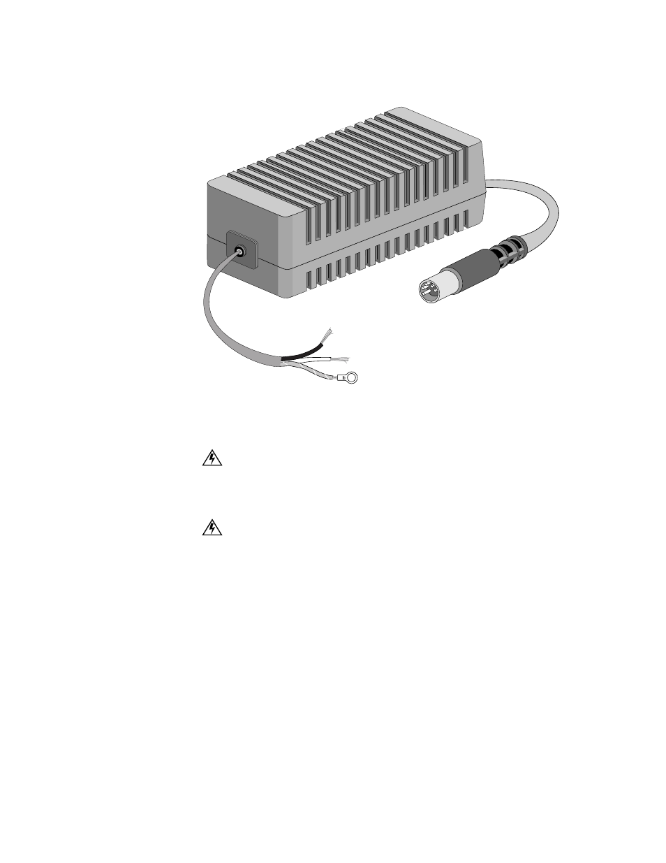
To power the unit from a DC source, use part number 9-9100-028-1, shown in
Figure 2-3). Follow the procedures below to connect and disconnect the power
supply. The power connection procedure applies power to the unit.
Connecting the DC Power Supply
WARNING: Before completing any of the following steps and to prevent short-circuit
or shock hazards, ensure that power removed from the DC circuit. To ensure that all
power is Off, locate the circuit breaker on the panel board that services the DC circuit,
switch the circuit breaker to the Off position, and tape the switch handle of the circuit
breaker in the Off position.
WARNING: When installing the unit, the ground connection must always be made first
and disconnected last.
1
Ensure that power is removed from the 48 volt source as indicated in the first
warning above.
2
Connect the green/yellow chassis ground wire of the DC power supply to the
ground lug or screw of the 48 volt source.
3
Connect the black (+) wire of the DC power supply to the return screw of the 48
volt source.
4
Connect the white (
−
) wire of the DC power supply to the
−
48 volt screw of the
48 volt source.
5
Connect the DC power supply to the MultiPro unit.
6
Apply power to the circuit. This applies power to the MultiPro unit.
DC INPUT
20 to 60VDC
2.7A MAX
(BLK + )(WHT
- )
(GRN/YEL CHAS GND)
Black +
White -
Green/Yellow Chassis Ground
Figure 2-3 DC Power Supply for the 9101, 9111, and 9211