9111 port 1 t1 option, Switch s1 – Verilink 9000 Series (34-00271) Product Manual User Manual
Page 47
9111 Connections
25
9111
Port 1
T1 Option
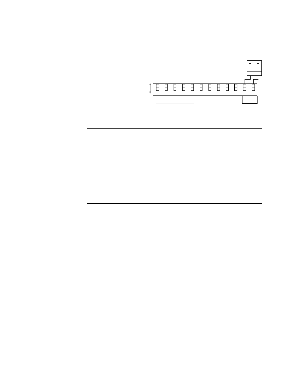
This section describes the 9111 Internal T1 Card. The card is a one-port T1
interface card for the 9111 MultiPro series unit. The module has an RJ-48
connector and is located above the supervisory port as shown in Figure 2-4. The
internal T1 card is configured using the switches located on the rear panel.
Switch S1
.
Switch S1 is a 12-position
DIP switch located on the
rear panel of the 9111. This
switch provides the
configuration parameters
shown in Table 2-9 and
Table 2-10
Table 2-9 Switch S1
1-5
DSOs Assigned: These five positions select the bit rate and the number of DSOs
assigned to the channel (see Table 2-10).
6
Rate Multiplier: Sets the multiplier for the input timing (see Table 2-10). The unit
operates at any data rate that is a multiple of 56 or 64 kbps.
7
Channel Assignment: The Contiguous mode assigns the channels as a block
beginning at DS0 channel 1. If Alternate is selected, channel assignments are made
with an idle channel following each data channel.
8
Timing Source: This switch determines the unit’s clocking source.
9
Network Coding: B8ZS or AMI. Because AMI mode is sensitive to zero-bit density,
B8ZS is recommended for a more robust configuration.
10
Network Framing: D4 or ESF only
11, 12 Network LBO: These switches set the network signal level (in decibels) of data
transmitted towards the T1 facility. The signal level is determined as shown in Figure 2-5.
6
5
4
3
1
2
5
6
k
b
p
s
A
lt
er
n
at
e
6
4
k
b
p
s
C
o
n
ti
g
u
o
u
s
A
B
N
et
w
o
rk
C
lo
c
k
(L
o
o
p
ed
)
In
te
rn
a
l
C
lo
ck
(M
as
te
r)
D
4
E
S
F
B
8
Z
S
A
M
I
LBO
Network
A
A
B
A
B
A
B
B
0
-22.5
-7.5
-15
12
11
9
10
8
7
Figure 2-5 Switch S1
DS0s Assigned
(see Table 2-10)