Physical description – Nortel Networks 1000 User Manual
Page 778
778
NTAK10 2.0 Mb DTI card
ATTENTION
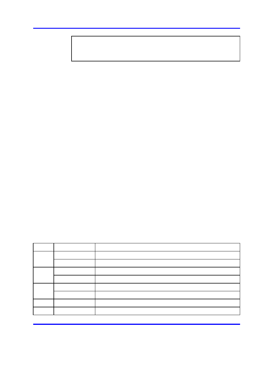
IMPORTANT!
Each Media Gateway that has a digital trunk must have a clock controller
clocked to an external reference clock.
Note:
Clocking slips can occur between systems that are clocked from
different COs, if the COs are not synchronized. The slips can degrade
voice quality.
The NTAK10 2.0 Mb DTI card is a digital trunk card that provides an
IPE-compatible 2.0 Mb DTI interface for the CS 1000 system. This circuit
card includes an on-board clock controller that can be manually switched
in or out of service.
The NTAK10 is installed only in the Media Gateway. It is not supported in
the Media Gateway Expansion. Up to four digital trunk cards are supported
in each Media Gateway. The NTAK10 card can be installed in slots 1, 2, 3,
and 4 of the Media Gateway.
Physical description
The 2 Mb DTI pack uses a standard 9.5" by 12.5", multi-layer printed
circuit board. The faceplate is 7/8" wide and contains six LEDs.
The LEDs operate as follows:
•
After the card is plugged in, the LEDs (a-e) are turned on by the
power-up circuit. The clock controller LED is independently controlled
by its own microprocessor.
•
After initialization, the LEDs (a-e) flash three times (0.5 seconds on,
0.5 seconds off) and then individual LEDs go into appropriate states,
as shown in
Table 329 "NTAK10 LED states" (page 778)
.
Table 329
NTAK10 LED states
LED
State
Definition
DIS
On (Red)
The NTAK10 circuit card is disabled.
Off
The NTAK10 is not in a disabled state.
OOS
On (Yellow)
The NTAK10 is in an out-of-service state.
Off
The NTAK10 is not in an out-of-service state.
NEA
On (Yellow)
A near end alarm state has been detected.
Off
No near end alarm.
FEA
On (Yellow)
A far end alarm state has been detected.
Off
No far end alarm.
Nortel Communication Server 1000
Circuit Card Reference
NN43001-311
02.06
Standard
27 August 2008
Copyright © 2003-2008 Nortel Networks
.