Option switch settings, Baud rate, Address – Nortel Networks 1000 User Manual
Page 735
Configuring the QSDI paddle board
735
Once the board has been installed, the system software must be
configured to recognize it. Instructions for doing this are found in the
section titled
“Software service changes” (page 728)
.
Option switch settings
Baud rate
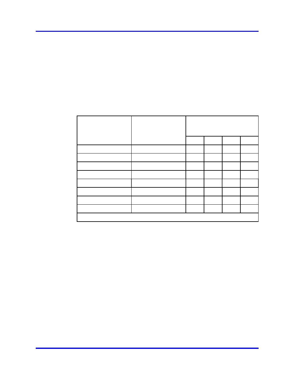
Switches SW13, SW10, SW11, and SW12 determine the baud rate for
ports 1, 2, 3, and 4, respectively. See the settings for these switches in
Table 292 "NT8D41BA baud rate switch settings" (page 735)
.
Table 292
NT8D41BA baud rate switch settings
SW13 (port 1),
SW10 (port 2),
SW11 (port 3), SW12 (port 4)
Baud
rate
Baud Clock
(kHz)
1
2
3
4
150
2.40
on
off
on
on
300
4.80
on
on
off
on
600
9.60
on
off
off
on
1,200
19.20
on
on
on
off
2,400
38.40
on
off
on
off
4,800
76.80
on
on
off
off
9,600
153.60
on
off
off
off
19,200*
307.20
on
on
on
on
* For future use.
Address
Switch SW15 or SW16 and logic on the card always address the four
UARTs using a pair of addresses: 0 and 1, 2 and 3 through 14 and 15.
The settings for both switches are shown in
address switch settings" (page 736)
. To avoid system problems,
switches SW15 and SW16 must not be configured identically.
"NT8D41BA QSDI paddle board" (page 731)
displays SW15 and SW16.
Nortel Communication Server 1000
Circuit Card Reference
NN43001-311
02.06
Standard
27 August 2008
Copyright © 2003-2008 Nortel Networks
.