Configuring the qsdi paddle board – Nortel Networks 1000 User Manual
Page 734
734
NT8D41BA Quad Serial Data Interface Paddle Board
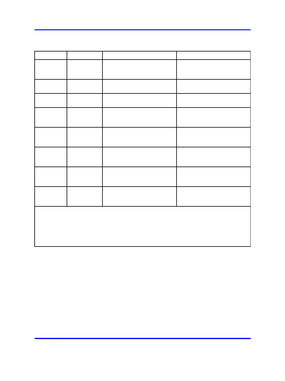
Table 291
Connectors J1, J2, J3, and J4 pin assignments
Pin #
Signal
Purpose in DTE mode
Purpose in DCE mode
1
D
C
D
Data Carrier detect (Note 1)
Data Carrier detect (Not used)
2
R
D
Transmitted data
Received data
3
T
D
Received data
Transmitted data
4
D
T
R
Data terminal ready
Data terminal ready (Note 2)
5
G
N
D
Signal Ground
Signal Ground
6
D
S
R
Data set ready (Note 1)
Data set ready
7
R
T
S
Request to send (Not Used)
Request to send (Note 2)
8
C
T
S
Clear to send (Note 1)
Clear to send
Note 1: In DTE mode the signals CD, DSR, and CTS are tied to +12 volts to signify that the port on
the QSDI paddle board is always ready to transmit and receive data. This mode is set to connect
to a terminal device (DTE).
Note 2: In DCE mode the signals DTR and RTS are tied to +12 volts to signify that the port on the
QSDI paddle board is always ready to transmit and receive data. This mode is set to connect
to a modem device (DCE).
Configuring the QSDI paddle board
Configuring the QSDI paddle board to work in a Meridian 1 system
consists of setting these option switches for each serial port:
•
Baud rate
•
Port address
•
DTE/DCE mode
The QSDI paddle board has fourteen option switches, SW2–13, SW15-16.
Figure 249 "NT8D41BA QSDI paddle board" (page 731)
identifies the
location of option switches on the QSDI paddle board. Learn how to set
these switches in the following sections.
Nortel Communication Server 1000
Circuit Card Reference
NN43001-311
02.06
Standard
27 August 2008
Copyright © 2003-2008 Nortel Networks
.