Ntak09 dti/pri power on self-test – Nortel Networks 1000 User Manual
Page 762
762
NTAK09 1.5 Mb DTI/PRI card
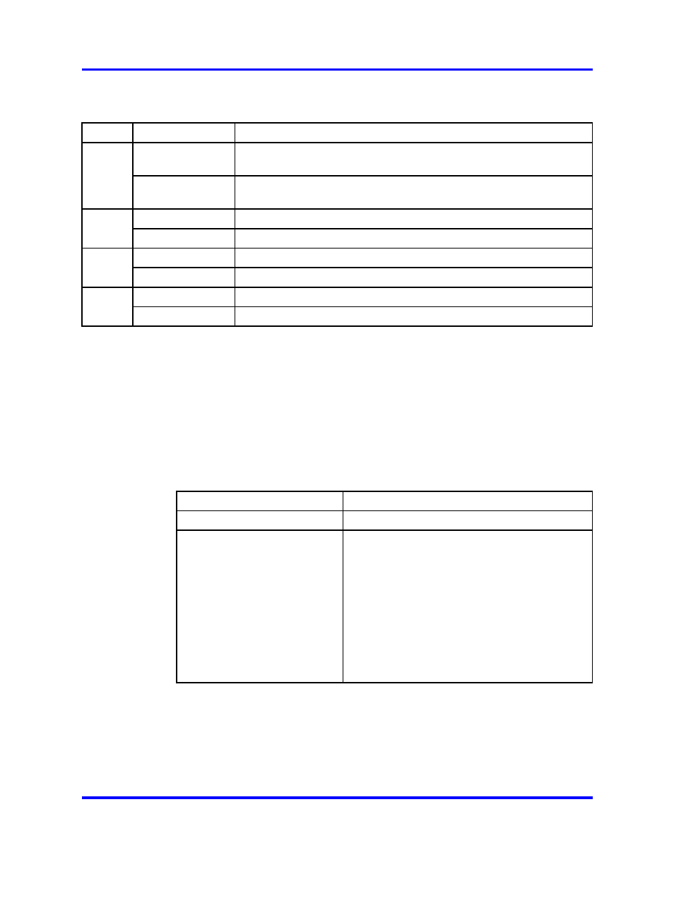
Table 317
NTAK09 LED states (cont’d.)
LED
State
Definition
On (Green)
The NTAK09 circuit card is in an active state. No alarm states exist,
the card is not disabled, and it is not in a loopback state.
ACT
Off
An alarm state or loopback state exists, or the card has been
disabled. See the other LEDs for more information.
On (Red)
A red-alarm state has been detected.
RED
Off
No red alarm.
On (Yellow)
A yellow alarm state has been detected.
YEL
Off
No yellow alarm.
On (Green)
NTAK09 is in loop-back mode.
LBK
Off
NTAK09 is not in loop-back mode.
NTAK09 DTI/PRI power on self-test
When power is applied to the NTAK09 DTI/PRI circuit card, the card
performs a self-test. The LEDs directly associated with the NTAK09 circuit
card are DIS, ACT, RED, YEL, and LBK. The clock controller LED is also
included in the power on self-test.
Table 318 "NTAK09 LED states during
provides the state of the NTAK09 LEDs during the
self-test procedure.
Table 318
NTAK09 LED states during self-test
Action
LED State
Power up system
Top five LEDs light for eleven seconds.
Self-test in progress
Top five LEDs go out for one second.
If the self-test passes, the top five LEDs flash
on and off three times.
If the self-test detects a partial failure, the top
five LEDs flash on and off five times.
When the self-test is completed, the LEDs are
set to their appropriate states.
When power is applied to the NTAK09 DTI/PRI circuit card, the card
performs a self-test. The LEDs directly associated with the NTAK09 circuit
card are DIS, ACT, RED, YEL, and LBK. The clock controller LED is also
included in the power on self-test.
Table 319 "NTAK09 LED states during
provides the state of the NTAK09 LEDs during the
self-test procedure.
Nortel Communication Server 1000
Circuit Card Reference
NN43001-311
02.06
Standard
27 August 2008
Copyright © 2003-2008 Nortel Networks
.