Nortel Networks 1000 User Manual
Page 476
476
NT8D09 Analog Message Waiting Line card
other IPE ports. LD 97 is used to configure the system for port-to-port loss.
See Software Input/Output Reference — Administration (NN43001-611) for
LD 97 service change instructions.
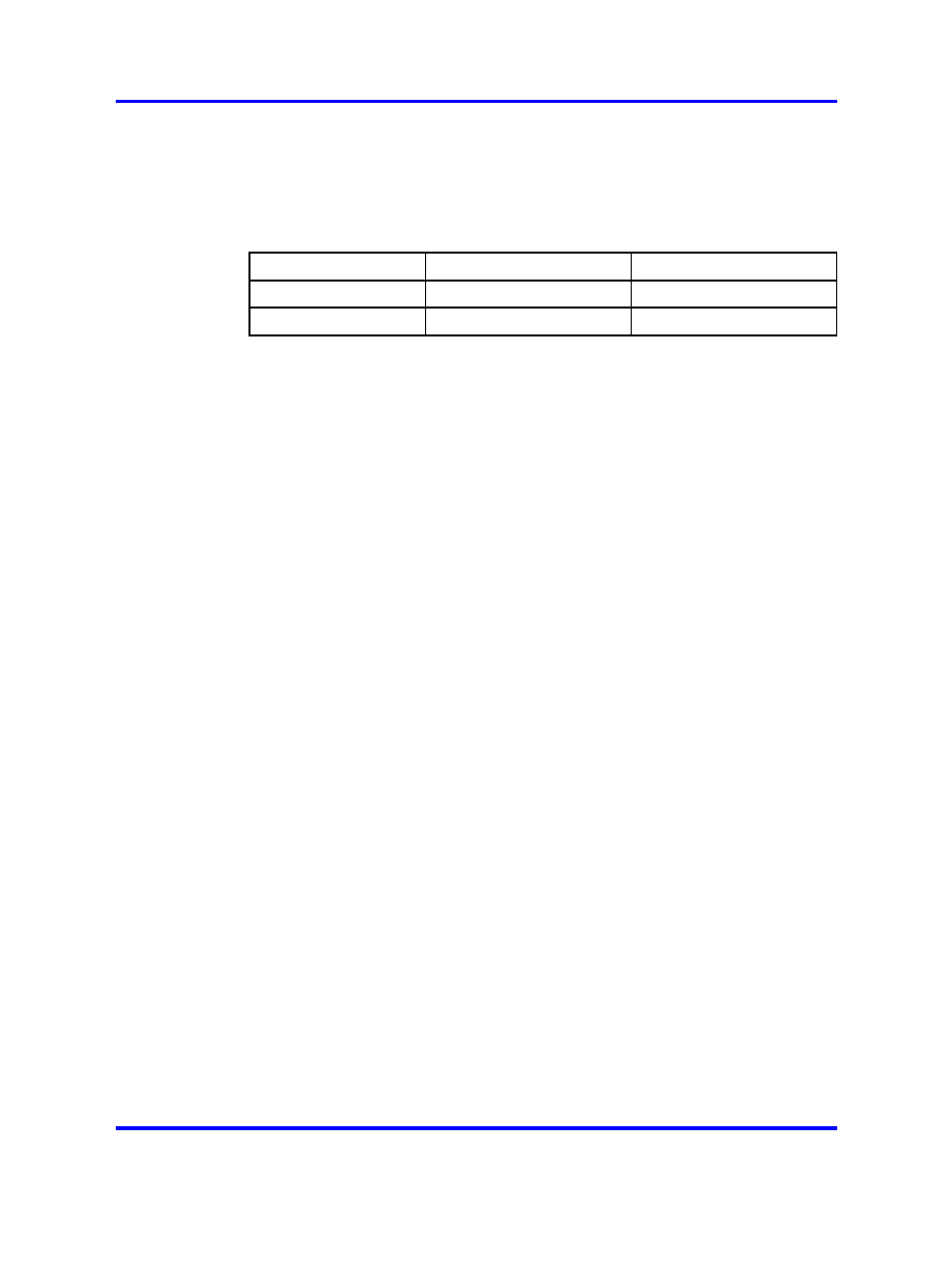
Table 200
Transmission Profile Changes
Vintage
A/D convertor gain
D/A convertor gain
Previous to AK
–3.5 dB
–2.5 dB
AK and later
–3.5 dB
–0.5 dB
The analog message waiting line card brings the 16 phone lines to the IPE
backplane through a 160-pin connector shroud. The backplane is cabled
to the I/O panel on the rear of the module, which is then connected to the
MDF by 25-pair cables.
Telephone lines from station equipment cross connect to the analog
message waiting line card at the MDF using a wiring plan similar to that
used for trunk cards. A typical connection example is shown in
"Analog message waiting line card - typical cross connection example"
(page 479)
, and
Table 201 "Analog message waiting line card - backplane
shows the I/O pin designations at the backplane
connector. This connector is arranged as an 80-row by 2-column array of
pins. Normally, these pin positions are cabled to 50-pin connectors at the
I/O panel in the rear of each module for connection with 25-pair cables to
the cross-connect terminal.
The information in
Table 201 "Analog message waiting line card -
is provided as a reference and diagnostic
aid at the backplane, since the cabling arrangement may vary at theI/O
panel. See Communication Server 1000M and Meridian 1 Large System
Installation and Configuration (NN43021-310) for cable pinout information
at the I/O panel.
Nortel Communication Server 1000
Circuit Card Reference
NN43001-311
02.06
Standard
27 August 2008
Copyright © 2003-2008 Nortel Networks
.