Dte/dce/fiber mode, Table 293 "nt8d41ba – Nortel Networks 1000 User Manual
Page 736
736
NT8D41BA Quad Serial Data Interface Paddle Board
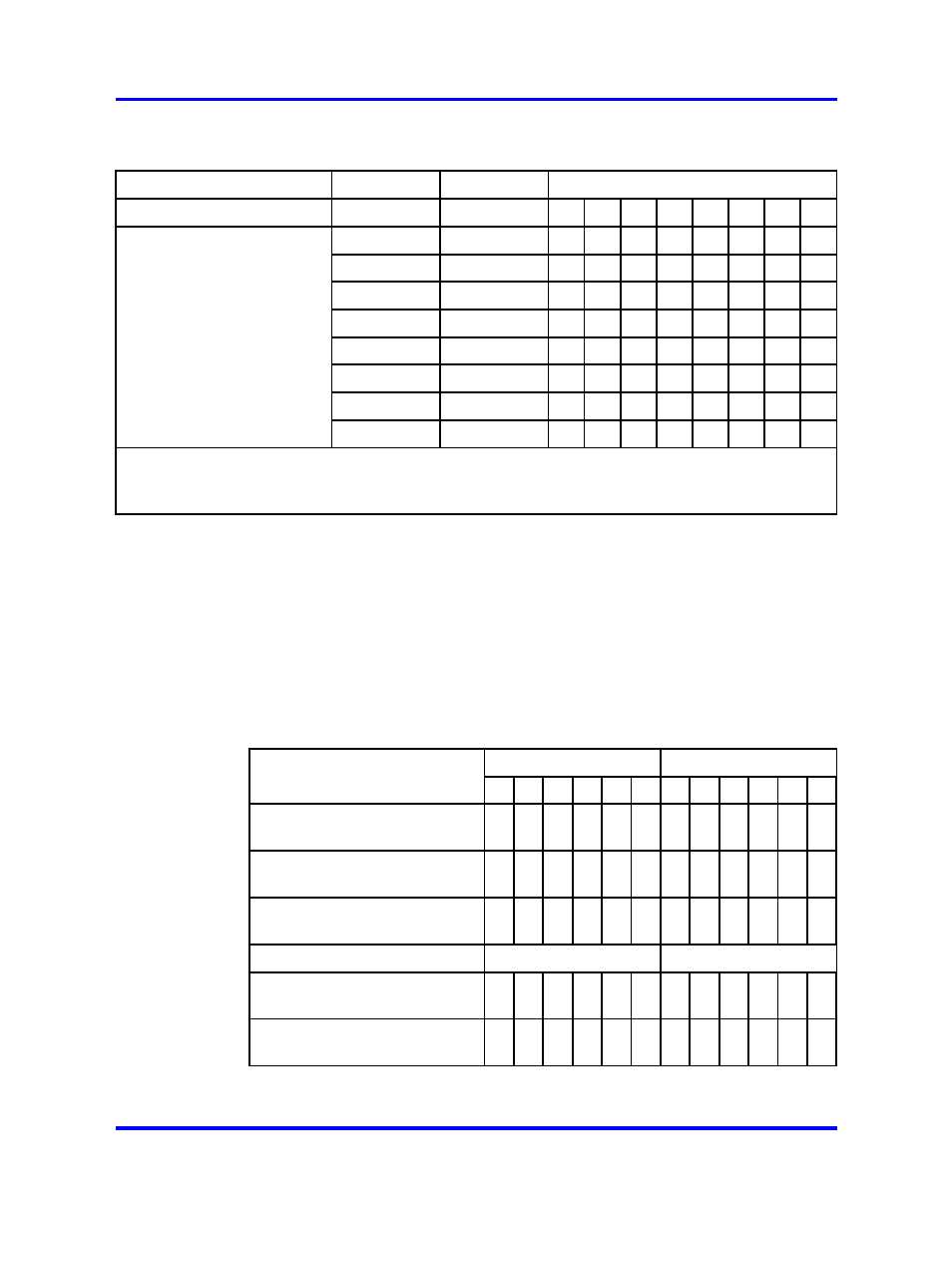
Table 293
NT8D41BA address switch settings
SW15
Port 1
Port 2
Switch settings
SW16
Port 3
Port 4
1*
2
+
3
4
5
6
7
8
0
1
E
X
off
off
off
off
off
off
Device
2
3
E
X
off
off
off
off
off
on
4
5
E
X
off
off
off
off
on
off
pair
6
7
E
X
off
off
off
off
on
on
8
9
E
X
off
off
off
on
off
off
addresses
10
11
E
X
off
off
off
on
off
on
12
13
E
X
off
off
off
on
on
off
14
15
E
X
off
off
off
on
on
on
* To enable ports 1 and 2, set SW15 position 1 to ON. To enable ports 3 and 4, set SW16
position 1 to ON.
+ For each X, the setting for this switch makes no difference, because it is not used.
DTE/DCE/Fiber mode
Each serial port can be configured to connect to a terminal (DTE
equipment), a modem (DCE equipment), or a Fiber Superloop Network
card. Instructions for setting the switches SW2, SW3, SW4, SW5, SW6,
SW7, SW8, and SW9 are shown in
Table 294 "NT8D41BA DTE/DCE/Fiber
Figure 249 "NT8D41BA QSDI paddle board"
shows the location of these switches on the paddleboard.
Table 294
NT8D41BA DTE/DCE/Fiber switch settings
Port 1 — SW 3
Port 1 —SW 2
Mode
1
2
3
4
5
6
1
2
3
4
5
6
DTE (terminal)
on on on of
f
on of
f
of
f
on of
f
on of
f
on
DCE (modem)
of
f
of
f
of
f
on of
f
on on of
f
on of
f
on of
f
NT1P61 (Fiber)
on on on on on of
f
on on on of
f
on of
f
Port 2 — SW 5
Port 2 — SW4
DTE (terminal)
on on on of
f
on of
f
of
f
on of
f
on of
f
on
DCE (modem)
of
f
of
f
of
f
on of
f
on on of
f
on of
f
on of
f
Nortel Communication Server 1000
Circuit Card Reference
NN43001-311
02.06
Standard
27 August 2008
Copyright © 2003-2008 Nortel Networks
.