Nortel Networks 1000 User Manual
Page 54
54
Overview
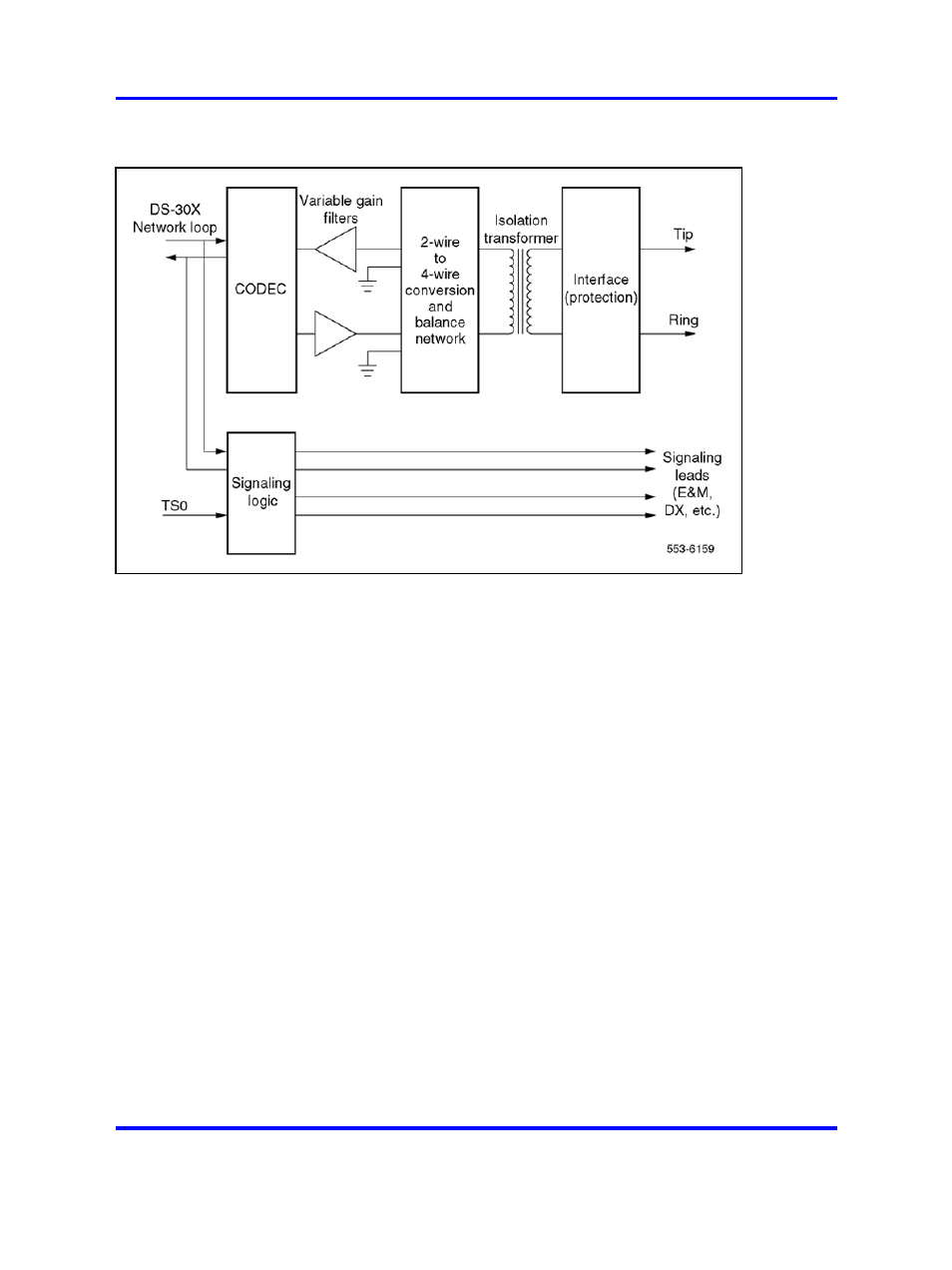
Figure 14
Typical trunk interface unit block diagram
Coder/Decoder circuit
The coder/decoder (codec) performs Analog
to Digital (A/D) and Digital to Analog (D/A) conversion of the line analog
voiceband signal to and from a digital PCM signal. This signal can be
coded and decoded using either the A-Law or the µ-Law companding
algorithm. On some trunk cards the decoding algorithm depends of the
type of codec installed when the board is built. On others, it is an option
selected using a software overlay.
Variable gain filters
Audio signals received from the analog phone
trunk are passed through a low-pass A/D monolithic filter that limits the
frequency spread of the input signal to a nominal 200–3400 Hz bandwidth.
The audio signal is then applied to the input of the codec. Audio signals
coming from the CODEC are passed through a low-pass A/D monolithic
filter that integrates the amplitude modulated pulses coming from the
CODEC, and then filters and amplifies the result.
On some of the trunk cards, the gain of these filters can be programmed
by the system controller. This allows the system to make up for line losses
according to the loss plan.
Balancing network
Depending on the card type, the balancing
network is capable of providing either a 600 ohm or a 900 ohm (or both)
impedance matching network. It also converts the 2-wire transmission path
Nortel Communication Server 1000
Circuit Card Reference
NN43001-311
02.06
Standard
27 August 2008
Copyright © 2003-2008 Nortel Networks
.