Electrical specifications – Nortel Networks 1000 User Manual
Page 123
Electrical specifications
123
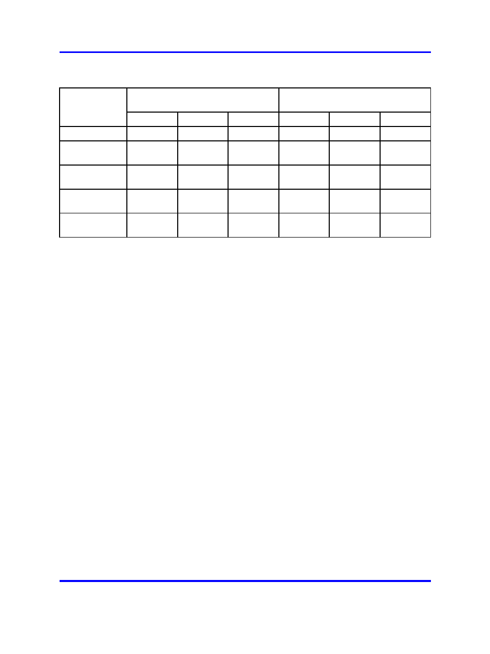
Table 49
OPS analog line card - cable loop resistance and loss
Cable loop loss (dB)
(non-loaded at 1kHz)
Cable loop resistance (ohms)
Cable length
26 AWG
24 AWG
22 AWG
26 AWG
24 AWG
22 AWG
847 m (2800 ft)
1.5
1.2
0.9
231.4
144.2
90
1411 m (4600
ft)
2.5
2
1.6
385.6
240.3
150
1694 m (5600
ft)
3
2.4
1.9
462.8
288.3
180
2541 m (8300
ft)
4.5
3.7
2.8
694.2
432.5
270
8469 m (27800
ft)
15
12.2
9.4
2313.9
1441.7
900
The loss plan for the NT1R20 OPS Analog Line Card determines
port-to-port loss for connections between an OPS analog line card unit
(port) and other ports.
The transmission properties of each line unit are characterized by the OPS
or ONS class-of-service assigned in the analog 500/2500-type telephone
administration program LD 10.
The loss plan for the OPS analog line card determines port-to-port loss
for connections between an OPS analog line card unit (port) and other
Meridian 1 PE or IPE ports.
The transmission properties of each line unit are characterized by the
OPS or ONS class-of-service assigned in the Single-line Telephone
Administration program (LD10).
Electrical specifications
This section lists the electrical characteristics of the NT1R20 OPS analog
line card.
The signaling and control portion of the card provides circuits that
establish, supervise, and take down call connections. These circuits work
with the system CPU to operate the line interface circuits during calls. The
circuits receive outgoing call signaling messages from the CPU and return
incoming call status information over the DS-30X network loop.
Nortel Communication Server 1000
Circuit Card Reference
NN43001-311
02.06
Standard
27 August 2008
Copyright © 2003-2008 Nortel Networks
.