Nortel Networks 1000 User Manual
Page 639
Physical description
639
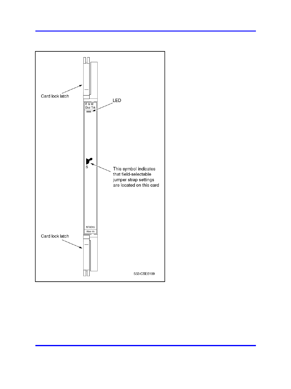
Figure 207
E and M Trunk card - faceplate
The E and M Trunk card mounts in slots 1, 2, 3, and 4 of the Media
Gateway and slots 7, 8, 9, and 10 of the Media Gateway Expansion. The
line interface and common multiplexing circuitry is mounted on a 31.75 cm
by 25.40 cm (12.5 in. by 10 in.) printed circuit board.
The E and M Trunk card connects to the backplane through a 160-pin
connector shroud. External equipment connects to the card at the back
of the Media Gateway using a 25-pin connector. Telephone lines from
station equipment cross connect to the OPS analog line card at the MDF
Nortel Communication Server 1000
Circuit Card Reference
NN43001-311
02.06
Standard
27 August 2008
Copyright © 2003-2008 Nortel Networks
.