Nortel Networks 1000 User Manual
Page 593
Electrical specifications
593
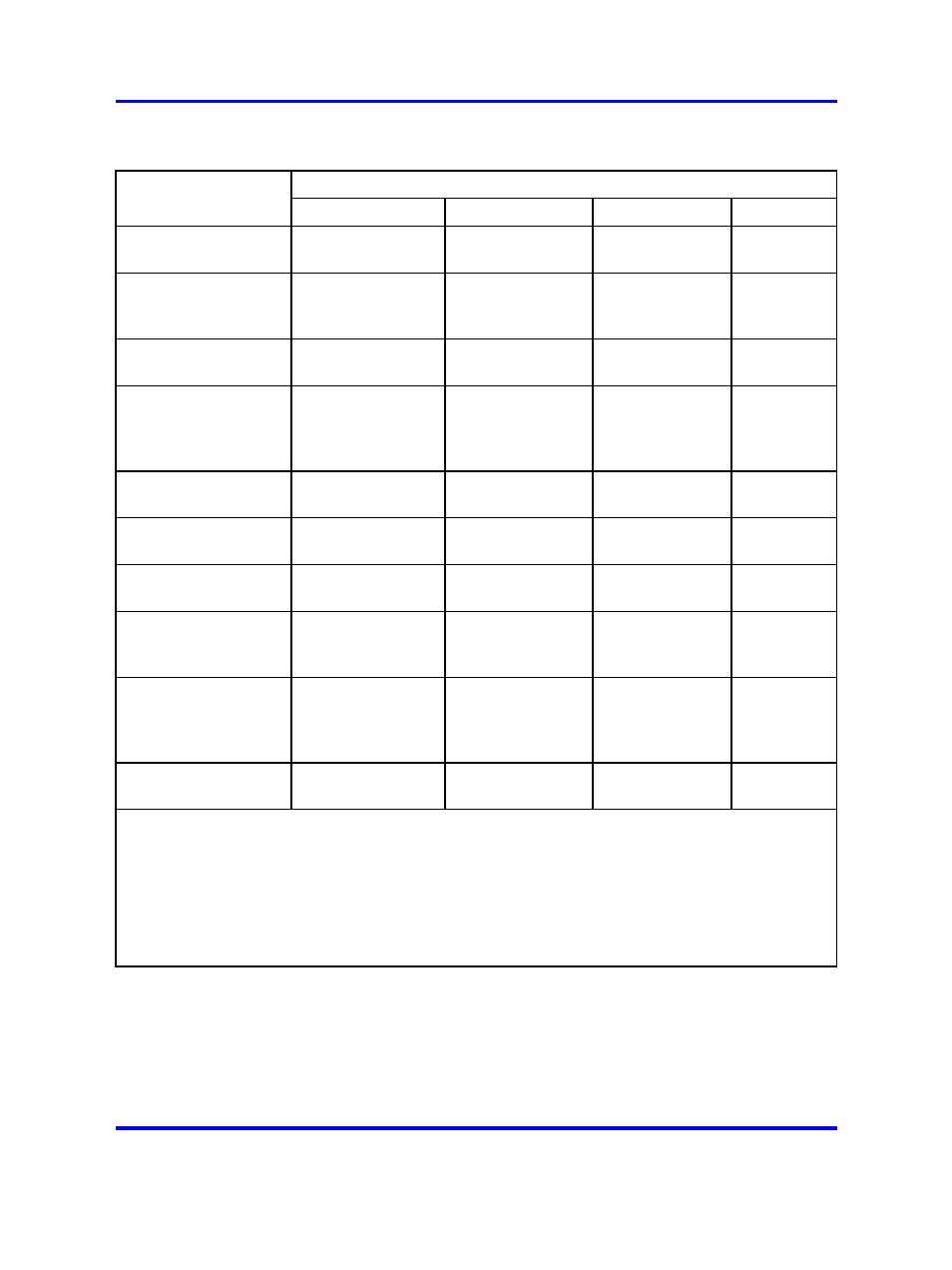
Table 207
Universal trunk card - trunk interface electrical characteristics
Trunk Types
Characteristic
CO / FX / WATS
DID / TIE
RAN
Paging
Terminal impedance
600 or 900 ohms
(Note 1)
600 or 900 ohms
(Note 1)
600/900 ohms
(Note 1)
600 ohms
Balance impedance
600 or 900 ohms
(Note 1), 3COM, or
3CM2 (Note 2)
600 or 900 ohms
(Note 1), 3COM,
or 3CM2 (Note 2)
N/A
N/A
Supervision type
Ground or loop
start (Note 3)
Loop start (with
ans sup) (Note 3)
Continuous,
level, or pulse
N/A
DC signaling loop
length (max)
1700-ohm loop
with near-end
battery of –42.75
V
2450-ohm loop
with near-end
battery of –44 V
600/900-ohm
loop
600 ohm
loop
Far-end battery
–42 to –52.5 V
(Note 4)
–42 to –52.5 V
–42 to –52 V
N/A
Minimum detected
loop current
20 mA
10 mA
10 mA
N/A
Ground potential
difference
±3 V
±3 V
±1 V
±1 V
Low DC loop
resistance during
outpulsing
<300 ohms
N/A
N/A
N/A
High DC loop
resistance
Ground start
ˇ
S 30k ohms;
loop start
ˇ
S 5M ohms
N/A ˇ
S
N/A
N/A
Ring detection
17 to 33 Hz 40 to
120 V rms
N/A
N/A
N/A
Note 1: Selected in software.
Note 2: Selected by jumper strap settings on card. Refer to
Table 224 "Jumper strap settings -
factory standard (NT8D14BA, NT8D14BB)" (page 607)
Table 225 "Jumper strap settings - extended
range (NT8D14BA, NT8D14BB, NT8D14BB)" (page 608)
, and
Table 226 "Trunk types - termination
impedance and balance network (NT8D14BA, NT8D14BB)" (page 608)
for details.
Note 3: For loop extender application, the maximum voltage applied between tip and ring is –105 V
±5%. The minimum dc loop resistance for this type of application is 1800 ohms.
Nortel Communication Server 1000
Circuit Card Reference
NN43001-311
02.06
Standard
27 August 2008
Copyright © 2003-2008 Nortel Networks
.