Installation, Table 80 – Nortel Networks 1000 User Manual
Page 190
190
NT5D11 and NT5D14 Lineside T1 Interface cards
Table 80
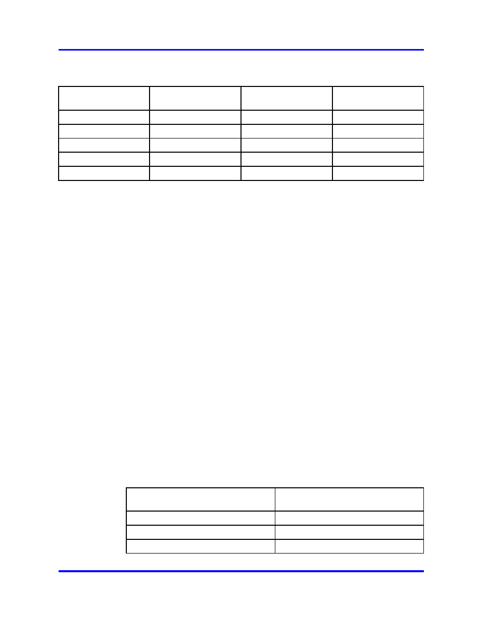
Lineside T1 card - CPE or CSU distance dip switch settings (Switch S2, positions 3 - 5)
Distance
S2 Switch
Position 3
S2 Switch
Position 4
S2 Switch
Position 5
0–133
On
Off
Off
134–266
Off
On
On
267–399
Off
On
Off
400–533
Off
Off
On
534–655
Off
Off
Off
Installation
This section describes how to install and test the Lineside T1 card.
When installed, the Lineside T1 card occupies two card slots. It can be
installed into an NT8D37 IPE module.
When installing the Lineside T1 card into NT8D37 IPE module, determine
the vintage level module. If the 25-pair I/O connectors are partially split
between adjacent IPE card slots, the Lineside T1 card works only in card
slots where Unit 0 of the motherboard card slot appears on the first pair of
the 25-pair I/O connector.
Certain vintage levels carry dedicated 25-pair I/O connectors only for card
slots 0, 4, 8, and 12. These vintage levels are cabled with only 16 pairs
of wires from each card slot to the I/O panel. Some of the 25-pair I/O
connectors are split between adjacent card slots. Other vintage levels
cable each card slot to the I/O panel using a unique, 24-pair connector on
the I/O panel. In these vintage levels, the Lineside T1 card can be installed
in any available pair of card slots. However, because of the lower number
of wire pairs cabled to the I/O panel in the lower vintage level, only certain
card slots are available to the Lineside T1 card.
See
Table 81 "Lineside T1 card - NT8D37 IPE module vintage level port
for the vintage level information for the NT8D37 IPE
modules.
Table 81
Lineside T1 card - NT8D37 IPE module vintage level port cabling
Vintage Level
Number of ports
cabled to I/O panel
NT8D37AA
16 ports
NT8D37BA
24 ports
NT8D37DC
16 ports
Nortel Communication Server 1000
Circuit Card Reference
NN43001-311
02.06
Standard
27 August 2008
Copyright © 2003-2008 Nortel Networks
.