Maestro configuration, Maestro input table – Grass Valley Maestro Master Control v.2.4.0 User Manual
Page 435
431
MAESTRO User Manual
Appendix C — Insertion of Keys and Audio Overs via GPI
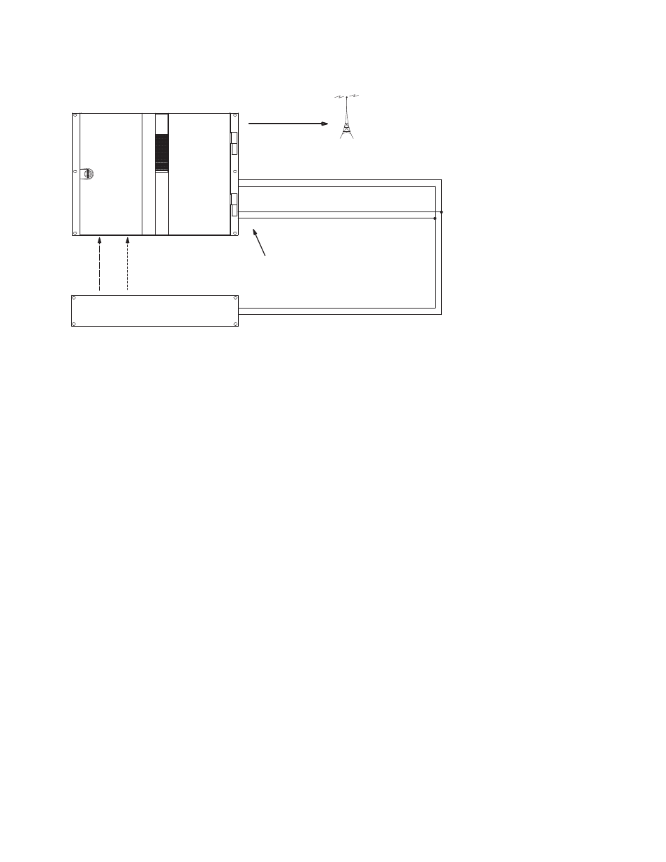
Figure 1. Connections between Maestro and EAS Receiver (Example)
EAS video is wired to one of the four Key Fill connectors on the Processor
rear panel; in this example, the connection is to the “KF4” input. Note that
this must be a digital video signal that is synchronous with the reference
used by Maestro.
EAS audio is wired to one of the two sets of audio over connectors on the
Processor rear panel; in this example, the connection is to the “Over B 1/2”
input. Note that this must be an AES (digital audio pair) signal.
The EAS TTL trigger port is connected to the GPIO connector on the Pro-
cessor rear panel. In this example, the connection is to Port 1 A & B and Port
2 A & B. These ports are associated with a specific keyer and mixer as
described below.
For pinouts of the GPIO connector, refer to the “GPIO” columns in Table 7
on page 75. For a representative schematic of the GPIO port, refer to the
“Input Photocoupler” section of Figure 41 on page 76.
Maestro Configuration
Maestro Input Table
Like all other Maestro sources, the EAS video and audio sources must be
entered on the Maestro Input table, where they are assigned a category/
number, a mnemonic, and an audio input configuration.
When wired directly into the Maestro (as described above), the EAS video
and audio sources will not appear as selectable input names on this table.
EAS Receiver
TTL
trigger
port
Transmitter
Keyer ON = 3-10 VDC, 4.25 mA max.
Maestro
GPIO Connections
See Note 1
1A
1B
Audio Over ON = 3-10 VDC, 4.25 mA max.
2A
2B
Note 1
Connections between Maestro
GPIO Connector and EAS receiver
trigger port are bipolar.
Key
Fill
4
Over
B In
1/2
Digital
video
Digital
audio
Program
- Maestro Master Control v.2.2.0 Maestro Master Control v.2.3.0 7600REF v5.0 Installation 7600REF v3.0.0.8 Installation 7600REF v3.0.0.8 7600REF v5.0 7620PX-5 Installation 2012 7620PX Installation 2012 Kayenne Installation v.3.0 Kayenne K-Frame Installation v.6.0 Kayenne K-Frame Installation v.7.0 Kayenne K-Frame Installation v.8.0 Karrera K-Frame S-Series Installation v.8.0 Karrera Video Production Center Installation v.6.0 Karrera Video Production Center Installation v.7.0 Karrera Video Production Center Installation v.4.1 Karrera Video Production Center Installation v.4.0 Kayenne Installation v.4.0 7620PX 2012 7620PX-5 2012 7620PX 2008 MVMC 3G VMCR 3G 8900F GeckoFlex Frames Concerto Compact Routing System Concerto Routing Matrix v.1.8.1 Concerto Routing Matrix v.1.7.6.1 Concerto Routing Matrix v.1.7.5 GPIO-4848 Jupiter Maestro Master Control v.2.0.0 Maestro Master Control Installation v.2.0.0 Maestro Master Control Installation v.2.3.0 Maestro Master Control Installation v.2.4.0 KayenneKayenne v.2.0 v.2.0 Maestro Master Control Installation v.1.5.1