Grass Valley Maestro Master Control v.2.4.0 User Manual
Page 115
111
MAESTRO User Manual
Section 2 — The Maestro Configuration Editor
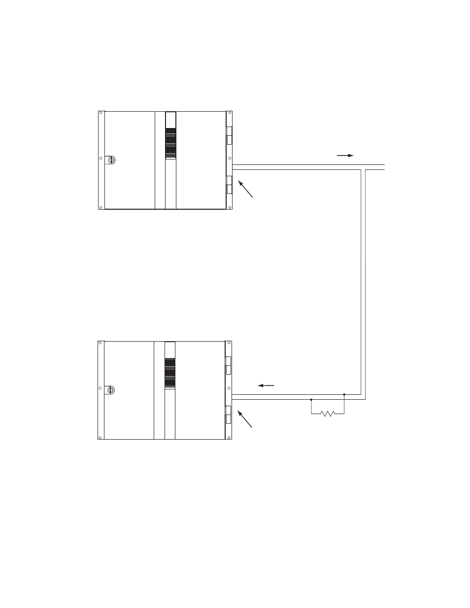
It is also possible for one Maestro processor to control another. See
.
Figure 58. Maestro-to-Maestro GPIO Connections
Note
Although the diagram above depicts two separate Maestro frames, the con-
trolling and controlled Maestro processor may be located in the same frame
Controlling Maestro
GPO Port/Relay
See Notes
1A
1B
Note 1
Connections between Maestro
GPIO Connector and controlled
external device are bipolar.
Note 2
Maximum current through Maestro relay = 250 mA
Maximum voltage for relay = 10 V
"Transition in Progress" signal
Controlled Maestro
GPI Port/Photocoupler
See Notes
1A
1B
Note 3
Maximum current through Maestro photocoupler = 4.25 mA
"High" range for photocoupler = 3-10 V
"Transition" signal
220 ohm
1/8 W
resistor
+
-
5 V
External
power
- Maestro Master Control v.2.2.0 Maestro Master Control v.2.3.0 7600REF v5.0 Installation 7600REF v3.0.0.8 Installation 7600REF v3.0.0.8 7600REF v5.0 7620PX-5 Installation 2012 7620PX Installation 2012 Kayenne Installation v.3.0 Kayenne K-Frame Installation v.6.0 Kayenne K-Frame Installation v.7.0 Kayenne K-Frame Installation v.8.0 Karrera K-Frame S-Series Installation v.8.0 Karrera Video Production Center Installation v.6.0 Karrera Video Production Center Installation v.7.0 Karrera Video Production Center Installation v.4.1 Karrera Video Production Center Installation v.4.0 Kayenne Installation v.4.0 7620PX 2012 7620PX-5 2012 7620PX 2008 MVMC 3G VMCR 3G 8900F GeckoFlex Frames Concerto Compact Routing System Concerto Routing Matrix v.1.8.1 Concerto Routing Matrix v.1.7.6.1 Concerto Routing Matrix v.1.7.5 GPIO-4848 Jupiter Maestro Master Control v.2.0.0 Maestro Master Control Installation v.2.0.0 Maestro Master Control Installation v.2.3.0 Maestro Master Control Installation v.2.4.0 KayenneKayenne v.2.0 v.2.0 Maestro Master Control Installation v.1.5.1