Grass Valley Maestro Master Control v.2.4.0 User Manual
Page 120
MAESTRO User Manual
116
5th Step: Input/Output Sets
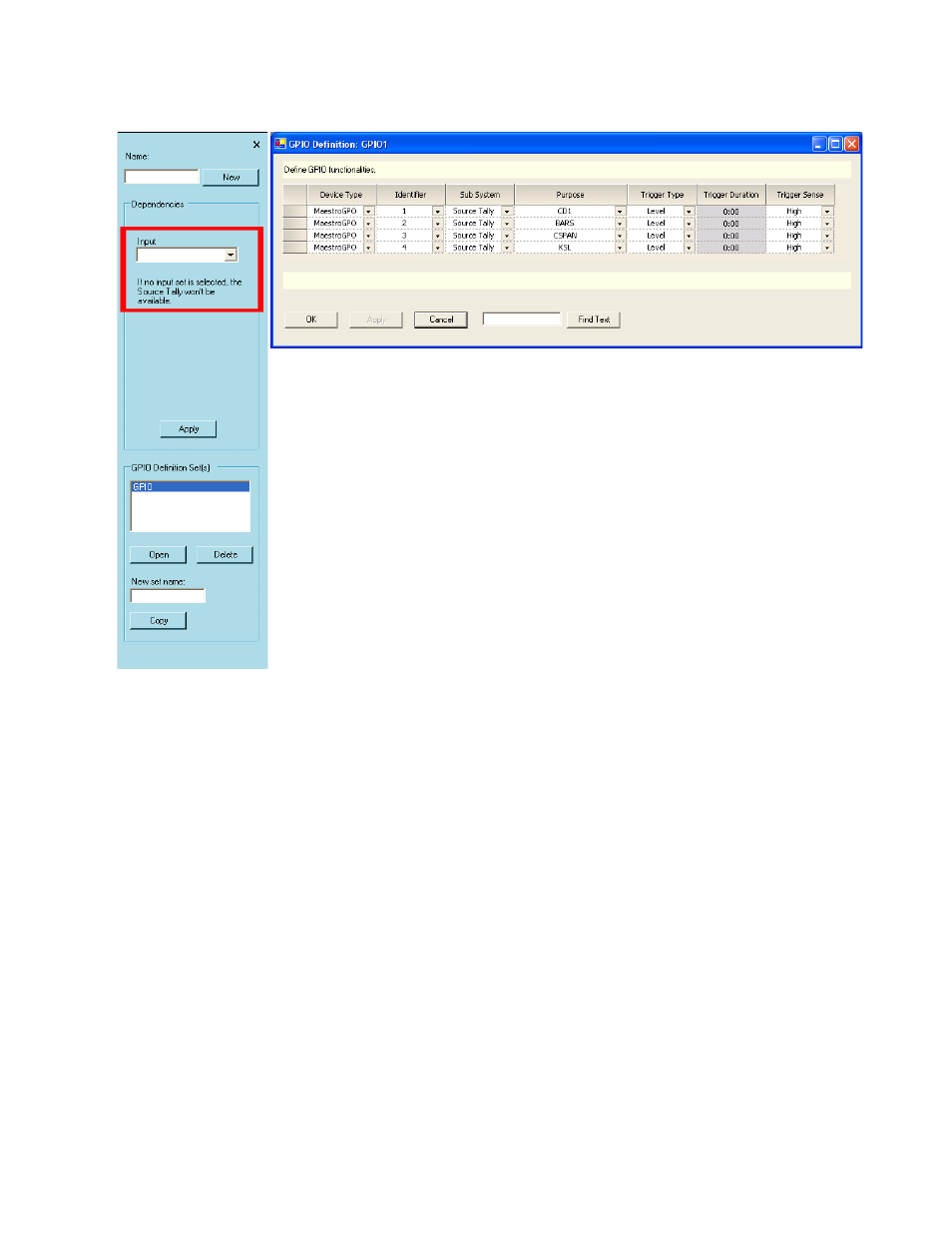
Figure 61. GPIO Definition Table for Source Tally Mode
Device Type
Select “MaestroGPO.”
Identifier
The numbers in this column refer to the 16 GPIO ports on the connector.
Any port from 1 to 16 can be selected in any order.
Trigger Type
Selections are Pulse or Level. When the defined source goes on-air, a
“Level” selection will cause the GPIO contact to go to and remain at the
state selected in the Trigger Sense column (described below).
Trigger Duration
This column applies only when “Pulse” has been selected as the Trigger
Type.
This manual is related to the following products:
- Maestro Master Control v.2.2.0 Maestro Master Control v.2.3.0 7600REF v5.0 Installation 7600REF v3.0.0.8 Installation 7600REF v3.0.0.8 7600REF v5.0 7620PX-5 Installation 2012 7620PX Installation 2012 Kayenne Installation v.3.0 Kayenne K-Frame Installation v.6.0 Kayenne K-Frame Installation v.7.0 Kayenne K-Frame Installation v.8.0 Karrera K-Frame S-Series Installation v.8.0 Karrera Video Production Center Installation v.6.0 Karrera Video Production Center Installation v.7.0 Karrera Video Production Center Installation v.4.1 Karrera Video Production Center Installation v.4.0 Kayenne Installation v.4.0 7620PX 2012 7620PX-5 2012 7620PX 2008 MVMC 3G VMCR 3G 8900F GeckoFlex Frames Concerto Compact Routing System Concerto Routing Matrix v.1.8.1 Concerto Routing Matrix v.1.7.6.1 Concerto Routing Matrix v.1.7.5 GPIO-4848 Jupiter Maestro Master Control v.2.0.0 Maestro Master Control Installation v.2.0.0 Maestro Master Control Installation v.2.3.0 Maestro Master Control Installation v.2.4.0 KayenneKayenne v.2.0 v.2.0 Maestro Master Control Installation v.1.5.1