Figure 56, Figure 57, Show exam – Grass Valley Maestro Master Control v.2.4.0 User Manual
Page 114
MAESTRO User Manual
110
5th Step: Input/Output Sets
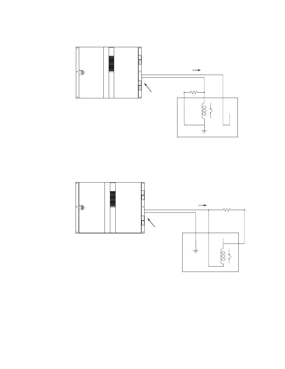
Figure 56. GPO Connections to External Controlled Device (Example1)
Figure 57. GPO Connections to External Controlled Device (Example 2)
Maestro
GPO Port/Relay
See Notes
1A
1B
Note 1
Connections between Maestro
GPIO Connector and controlled
external device are bipolar.
Note 2
Maximum current through Maestro relay = 250 mA
Maximum voltage for relay = 10 V
"Transition in Progress" signal
Controlled external device
+5 V
220 ohm
1/8 W
resistor
- Maestro Master Control v.2.2.0 Maestro Master Control v.2.3.0 7600REF v5.0 Installation 7600REF v3.0.0.8 Installation 7600REF v3.0.0.8 7600REF v5.0 7620PX-5 Installation 2012 7620PX Installation 2012 Kayenne Installation v.3.0 Kayenne K-Frame Installation v.6.0 Kayenne K-Frame Installation v.7.0 Kayenne K-Frame Installation v.8.0 Karrera K-Frame S-Series Installation v.8.0 Karrera Video Production Center Installation v.6.0 Karrera Video Production Center Installation v.7.0 Karrera Video Production Center Installation v.4.1 Karrera Video Production Center Installation v.4.0 Kayenne Installation v.4.0 7620PX 2012 7620PX-5 2012 7620PX 2008 MVMC 3G VMCR 3G 8900F GeckoFlex Frames Concerto Compact Routing System Concerto Routing Matrix v.1.8.1 Concerto Routing Matrix v.1.7.6.1 Concerto Routing Matrix v.1.7.5 GPIO-4848 Jupiter Maestro Master Control v.2.0.0 Maestro Master Control Installation v.2.0.0 Maestro Master Control Installation v.2.3.0 Maestro Master Control Installation v.2.4.0 KayenneKayenne v.2.0 v.2.0 Maestro Master Control Installation v.1.5.1