Freescale Semiconductor MPC5200B User Manual
Page 89
MPC5200B Users Guide, Rev. 1
2-44
Freescale Semiconductor
Pinout Tables
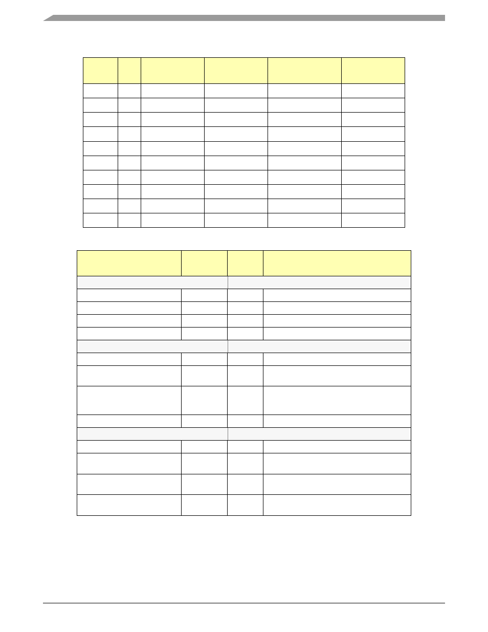
Table 2-16. USB Pin Functions
Pin
Name
Dir.
Reset
Configuration
GPIO
USB
2x UART4/5
USB_0
I/O
GPIO
USB1_OE
GPIO
USB_1
I/O
RST_CFG6
USB1_TXN
UART4_RTS
USB_2
I/O
RST_CFG7
USB1_TXP
UART4_TXD
USB_3
I
USB1_RXD
UART4_RXD
USB_4
I
USB1_RXP
UART4_CTS
USB_5
I
USB1_RXN
UART5_RXD
USB_6
I/O
GPIO
USB1_PORTPWR
UART5_TXD
USB_7
I/O
GPIO
USB1_SPEED
UART5_RTS
USB_8
I/O
GPIO
USB1_SUSPEND
UART5_CTS
USB_9
I/O
INTERRUPT
USB1_OVERCNT
INTERRUPT
Table 2-17. USB Pin Functions by Pin
PIN / BALL NUMBER
Function
Reset
Value
Description
Pin USB_0 Ball H01
GPIO
hi - z
GPIO
USB1
hi - z
USB1_OE
RESET Config.
hi - z
----
UART4, UART5
hi - z
GPIO
Pin USB_1 Ball H02
GPIO
hi - z
----
USB1
hi - z
USB1_TXN
USB1 Transmit Negative
RESET Config.
hi - z
RST_CFG6 -- sys_pll_cfg_0
bit =0 : f
system
= 16x SYS_XTAL_IN
bit =1 : f
system
= 12x SYS_XTAL_IN
UART4, UART5
hi - z
UART4_RTS
Pin USB_2 Ball H03
GPIO
hi - z
----
USB1
hi - z
USB1_TXP
USB1 Transmit Positive
RESET Config.
hi - z
RST_CFG7
(Pull bit low)
UART4, UART5
hi - z
UART4_TXD
Uart Transmit Data