4 spi status register -mbar + 0x0f05, Spi status register —mbar + 0x0f05 -6, Spi baud rate selection -6 – Freescale Semiconductor MPC5200B User Manual
Page 607: Spi status register -6, Spi status register
MPC5200B Users Guide, Rev. 1
17-6
Freescale Semiconductor
SPI Registers—MBAR + 0x0F00
17.3.4
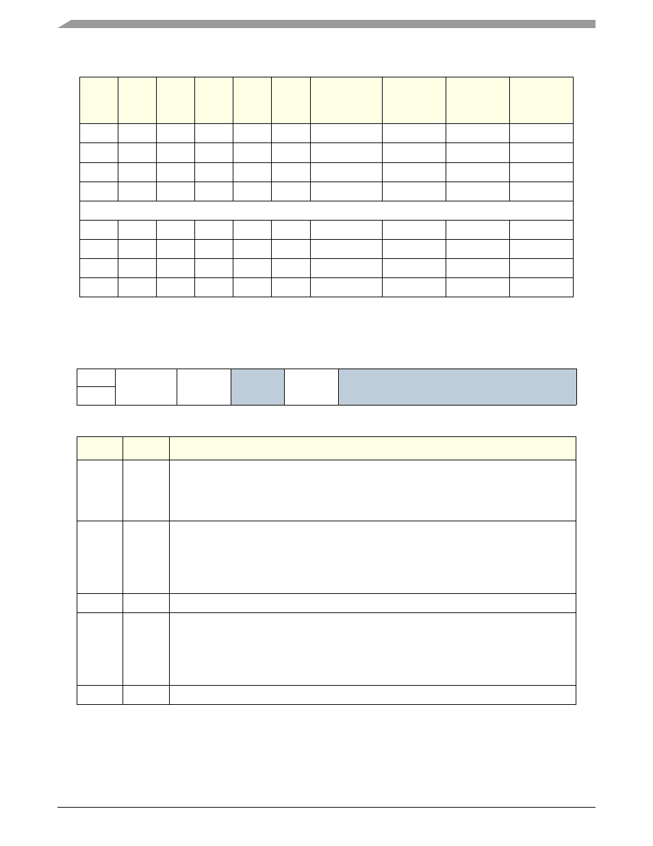
SPI Status Register —MBAR + 0x0F05
Table 17-7. SPI Baud Rate Selection
SPPR2 SPPR1 SPPR0
SPR2
SPR1
SPR0
SPI Module
Clock Divisor
Baud Rate
IPB 33.0
MHz
Baud Rate
IPB 66.0
MHz
Baud Rate
IPB 132.0
MHz
0
0
0
0
0
0
2
16.50 MHz
33.00 MHz
66.00 MHz
0
0
0
0
0
1
4
8.250 MHz
16.50 MHz
33.00 MHz
0
0
0
0
1
0
8
4.125 MHz
8.250 MHz
16.50 MHz
0
0
0
0
1
1
16
2.063 MHz
4.125 MHz
8.250 MHz
....
1
1
1
1
0
0
256
128.9 KHz
257.8 KHz
512.6 KHz
1
1
1
1
0
1
512
64.45 KHz
128.9 KHz
257.8 KHz
1
1
1
1
1
0
1024
32.23 KHz
64.45 KHz
128.9 KHz
1
1
1
1
1
1
2048
16.1 KHz
32.23 KHz
64.45 KHz
Table 17-8. SPI Status Register
msb 0
1
2
3
4
5
6
7 lsb
R
SPIF
WCOL
Reserved
MODF
Reserved
W
RESET:
0
0
0
0
0
0
0
0
Bit
Name
Description
0
SPIF
SPI Interrupt flag—bit sets after 8th SCK cycle in a data transfer. Bit is cleared by an SPISR
register read (with SPIF set) followed by an SPI data register read or write access.
0 = Transfer not yet complete
1 = New data copied to SPIDR
1
WCOL
Write Collision flag—bit indicates a serial transfer was in progress when the MCU tried to write
new data into the SPI data register. The flag is cleared automatically by an SPI status register
read (with WCOL set) followed by a SPI data register read or write access.
0 = Write collision did not occur
1 = Write collision occurred
2
—
Reserved
3
MODF
Mode Fault flag—bit sets if SS input goes low while SPI is configured as a master. Flag is cleared
automatically by an SPI status register read (with MODF set) followed by a SPI control register
1 write.
0 = Mode fault did not occur
1 = Mode fault occurred
4:7
—
Reserved