Timing diagram—multidrop mode -69, Figure 15-26 – Freescale Semiconductor MPC5200B User Manual
Page 587
MPC5200B Users Guide, Rev. 1
15-76
Freescale Semiconductor
PSC FIFO System
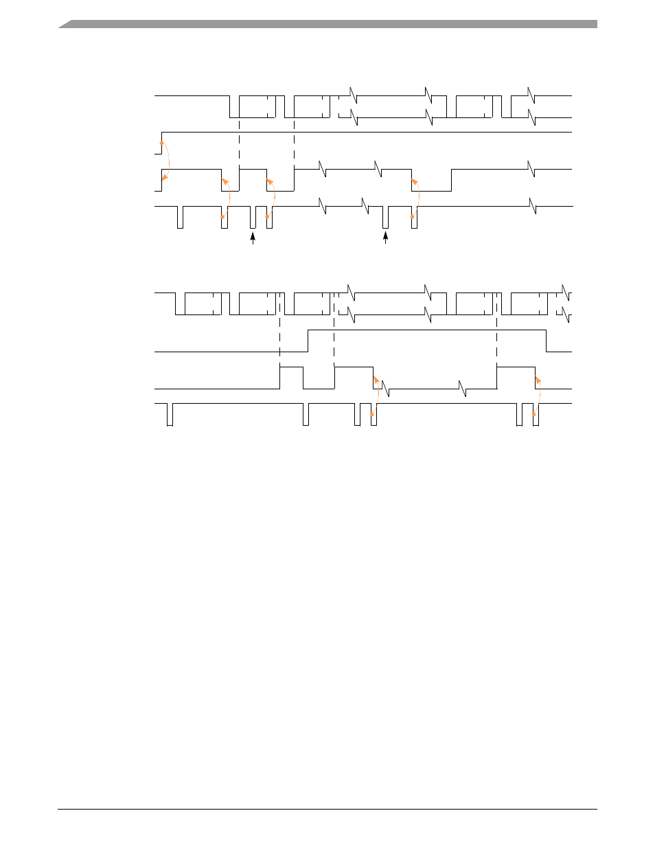
Figure 15-26. Timing Diagram—Multidrop Mode
A character sent from the master station consists of:
•
a start bit
•
a programmed number of data bits
•
an address/data (A/D) bit flag
— A/D=1 indicates an address character
— A/D=0 indicates a data character
•
a programmed number of stop bits
A/D polarity is selected through
should be programmed before enabling the transmitter and loading the corresponding data
bits into the Tx buffer.
In multidrop mode, the receiver continuously monitors the received data stream, regardless of whether it is enabled or disabled.
•
If the receiver is disabled, it sets the RxRDY bit and loads the character into the receiver holding register FIFO stack, provided the
received A/D bit is 1 (address tag). If the received A/D bit is 0 (data tag), the character is discarded.
•
If the receiver is enabled, all received characters are transferred to the CPU through the receiver holding register stack during read
operations.
In either case, data bits are loaded into the data portion of the stack while the A/D bit is loaded into the status portion of the stack normally
used for a parity error (
[PE]).
Framing error, overrun error, and break detection operate normally. The A/D bit takes the place of the parity bit. Parity is neither calculated
nor checked. Messages in this mode may still contain error detection and correction information. One way to provide error detection if 8-bit
characters are not required, is to use software to calculate parity and append it to the 5-, 6-, or 7-bit character.
ADD1
TxD
Transmitter
Enabled
SR [TxRDY]
C0
ADD2
1
1
internal
module
select
A/D
A/D
A/D
ADD1
RxD
Receiver
Enabled
SR[RxRDY]
C0
ADD2
1
1
internal
module
select
A/D
A/D
A/D
0
A/D
0
A/D
(C0)
Status Data
(ADD 2)
Status Data
ADD 1
Peripheral Station
Master Station
MR1n[PM] = 11
MR1n[PM] = 11
MR1n[PT] = 1
ADD 1
MR1n[PT] = 0
C0
MR1n[PT] = 2
ADD 2
MR1n[PM] = 11