Freescale Semiconductor MPC5200B User Manual
Page 101
MPC5200B Users Guide, Rev. 1
2-56
Freescale Semiconductor
Pinout Tables
Notes:
1.
The external bus clock (pci_clk) will be 1/2 the frequency of the internal bus clock (ipb_clk) at powerup. Therefore, 4 IPbus wait states
will translate to as little as 1 external wait state (i.e. peripheral must respond within 2 external clocks). The "slow" setting represents
48 IPbus clocks of wait, or 23 external clocks of wait External waits are "minus-1" because Chip Select may assert on falling edge
of external bus clock (dependant on internal timing).
2.
For muxed boot ROM types, the width of ALE_b & TS_b will be 2 IPbus clocks (i.e. 1 external clock). This represents the "wide ALE"
setting in the LocalPlus Controller (LPC). Care must be taken if these clock relationships are to be changed during the boot
process. For the 1-to-1 internal-to-external clock setting (which must be programmed by software into the CDM), be sure to change
the ALE width setting (in LPC) *after* adjusting the clock relationship. Any fetches to the boot device between these two settings will
result in ALE and TS being 2 external clocks wide.
3.
Only one boot mode can be enabled at a time. Large Flash and Most Graphics cannot be enabled at the same time. If neither Large
Flash or Most Graphics is enabled, boot will occur from the normal LocalPlus mode, either muxed or nonmuxed (depending on the
"boot_rom_type" configuration input).
Pin ETH_7 Ball N01
GPIO
hi - z
GPIO
Simple General Purpose Output
USB2
hi - z
USB2_TXN
USB Transmit Negative
ETH7 Wire
hi - z
GPIO
Simple General Purpose Output
ETH7 Wire / USB2
hi - z
USB2_TXN
USB Transmit Negative
ETH18 Wire w/o MD
hi - z
GPIO
Simple General Purpose Output
ETH18 Wire w/ MD
hi - z
ETH_MDIO
Ethernet Management Data I/O
EHT7 Wire, UART4e, J1850
hi - z
GPIO
Simple General Purpose Output
ETH7 Wire, J1850
hi - z
GPIO
Simple General Purpose Output
UART_4, UART5e, J1850
hi - z
GPIO
Simple General Purpose Output
UART5e, J1850
hi - z
GPIO
Simple General Purpose Output
J1850
hi - z
GPIO
Simple General Purpose Output
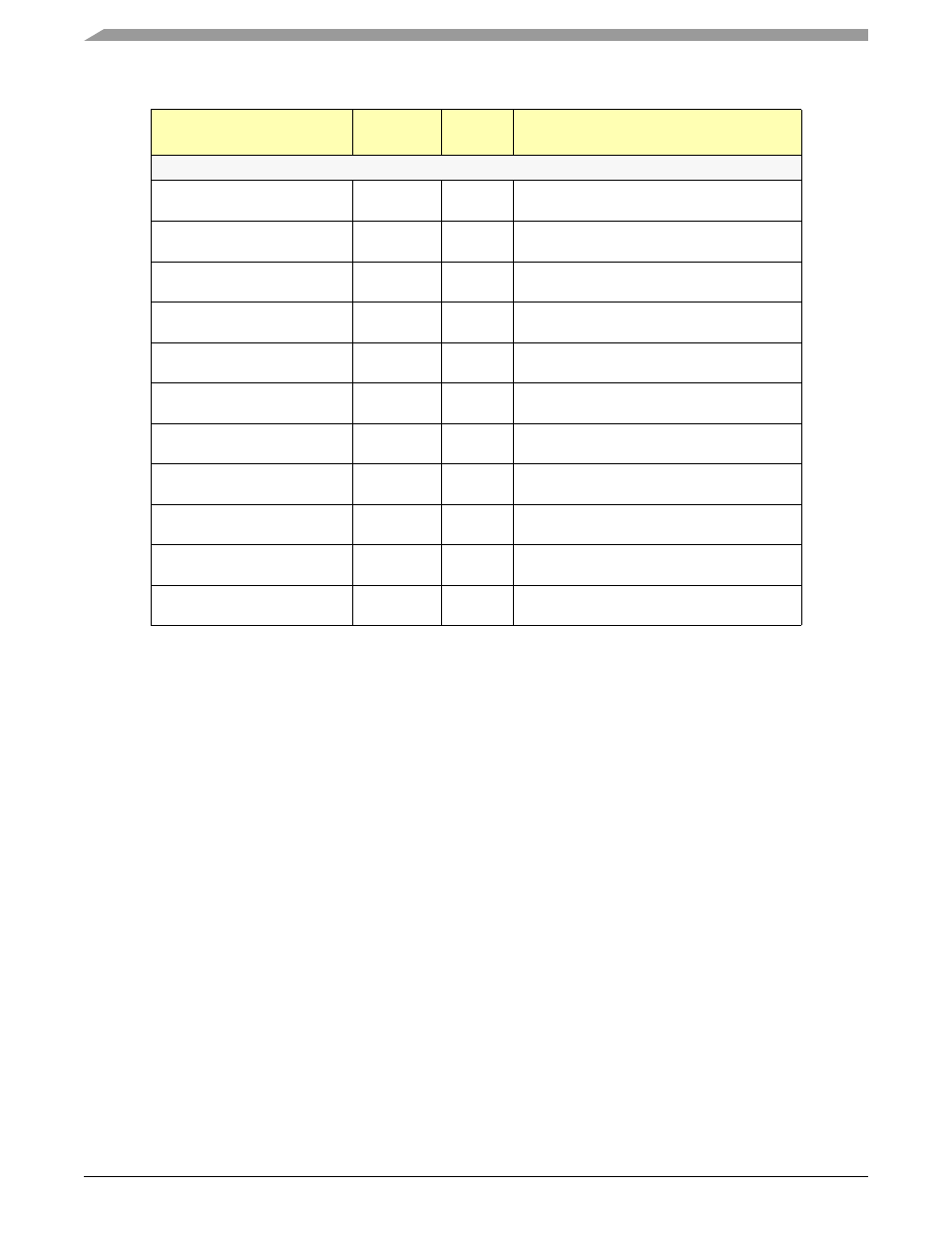
Table 2-20. Ethernet Output Functions by Pin (continued)
PIN / BALL NUMBER
Function
Reset
Value
Description