2 uart clock generation, 3 transmitting in uart mode, Uart clock generation -41 – Freescale Semiconductor MPC5200B User Manual
Page 557: Transmitting in uart mode -41, Clocking source diagram, An external clock source, Figure 15-2
MPC5200B Users Guide, Rev. 1
15-46
Freescale Semiconductor
PSC Operation Modes
Figure 15-2. Signal configuration for a PSC/RS-232 interface
15.3.1.2
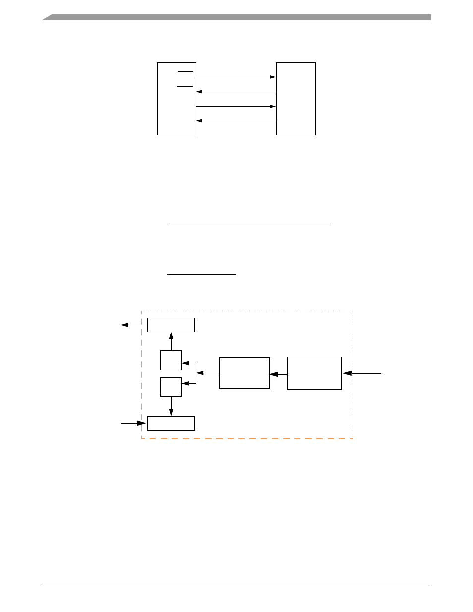
UART Clock Generation
IPB clock serves as the basic timing reference for the clock source generator logic, which consists of a Clock Generator and a programmable
16-bit divider dedicated to the PSC and a fix prescaler. The IPB clock passes through the prescaler (divide by 32 or 4) and then through 16-bit
divider of the concatenated
registers. See also
. Using a 66 MHz IPB clock and the 32 prescaler, the Baud-rate
calculation is as follows:
Let Baud rate = 9600, the divider can be calculated as follows:
Therefore
= 0x00 and
= 0xD7.
Figure 15-3. Clocking Source Diagram
15.3.1.3
Transmitting in UART Mode
After a hardware reset all PSC are in UART mode. The transmitter is enabled through the PSC command register (
). When it is ready to
accept a character, the PSC sets
[TxRDY]. The transmitter converts parallel data from the CPU to a serial bit-stream on TxD. It
automatically sends a start bit followed by:
•
the programmed number of data bits
•
an optional parity bit
•
the programmed number of stop bits
The lsb is sent first. Data is shifted from the Tx output on the falling edge of the clock source.
RTS
DO2
DI1
CTS
TxD
RxD
DI2
DO1
RS-232
PSC
Transceiver
Baud rate =
IPB Clock
32 x divider {CTUR:CTLR}
Divider =
66 MHz
32 x 9600
= 215(decimal) = 0x00D7
PSC
16-Bit
Divider
TxD
RxD
Tx
Rx
Rx Buffer
Tx Buffer
{CTUR:CTLR}
IPB
Clock
Prescaler
32 or 4