Freescale Semiconductor MPC5200B User Manual
Page 311
MPC5200B Users Guide, Rev. 1
10-14
Freescale Semiconductor
Registers
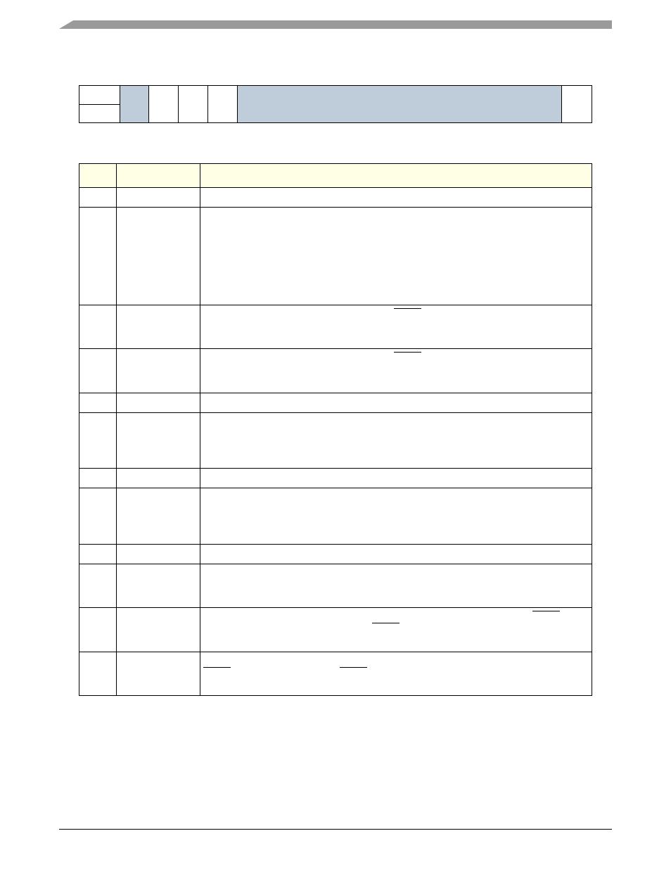
16
17
18
19
20
21
22
23
24
25
26
27
28
29
30
31 lsb
R
Rsvd
BME
PEE
SEE
Reserved
PR
W
RESET
0
0
0
0
0
0
0
0
0
0
0
0
0
0
0
1
Bits
Name
Description
0
Reserved
Unused bit. Software should write zero to this register.
1
Broken Master
Detected
(BM)
This bit is set when the PCI Arbiter detects a broken external PCI master.
Note: In case of broken master detection the external PCI request will be ignored until
external deassertion of PCI request or until a software reset (PCI Arbiter Softreset) or by
Hardreset is detected. After broken master detection (PCI bus idle for 16 clocks) the
arbiter will ignore any FRAME# assertion.
A CPU interrupt will be generated if the PCIGSCR[BME] bit is set. This is a RWC
(Read/WriteClear) bit: to clear it, software must write a ‘1’ at this position.
2
PERR
Detected
(PE)
This bit is set when the PCI Parity Error line, PERR, asserts (any device). A CPU interrupt
will be generated if the PCIGSCR[PEE] bit is set. This is a RWC (Read/WriteClear) bit: to
clear it, software must write a ‘1’ at this position.
3
SERR
Detected
(SE)
This bit is set when a PCI System Error line, SERR, asserts (any device). A CPU interrupt
will be generated if the PCIGSCR[SEE] bit is set. This is a RWC (Read/WriteClear) bit: to
clear it, software must write a ‘1’ at this position.
4
Reserved
Unused bit. Software should write zero to this register.
5:7
XL Bus_clk to
PCI_CLK
differential
(read only)
This bit field stores the XL bus clock to the PCI clock divide ratio. This field is read-only
and the reset value is determined by the PLL multiplier (either 1, 2, or 4). Software can
read these bits to determine a valid ratio. If the register contains a differential value that
does not reflect the PLL settings, the PCI controller could malfunction.
8:12
Reserved
Unused bits. Software should write zero to this register.
13:15
ipg_clk to
PCI_CLK
differential
(read only)
This bit field stores the Slave bus clock to the PCI clock divide ratio. This field is read-only
and the reset value is determined by the PLL multiplier (either 1, 2, or 4). Software can
read these bits to determine a valid ratio. If the register contains a differential value that
does not reflect the PLL settings, the PCI controller could malfunction.
16
Reserved
Unused bit. Software should write zero to this register.
17
Broken Master
Interrupt Enable
(BME)
This bit enables CPU Interrupt generation when a broken Master is detected. When
enabled, software must clear the BM status bit to clear the interrupt condition.
18
Parity Error
Interrupt Enable
(PEE)
This bit enables CPU Interrupt generation when the PCI Parity Error signal, PERR, is
sampled asserted. When enabled and PERR asserts, software must clear the PE status
bit to clear the interrupt condition.
19
System Error
Interrupt Enable
(SEE)
This bit enables CPU Interrupt generation when a PCI System Error is detected on the
SERR line. When enabled and SERR asserts, software must clear the SE status bit to
clear the interrupt condition.