Freescale Semiconductor MPC5200B User Manual
Page 566
PSC Operation Modes
MPC5200B Users Guide, Rev. 1
Freescale Semiconductor
15-55
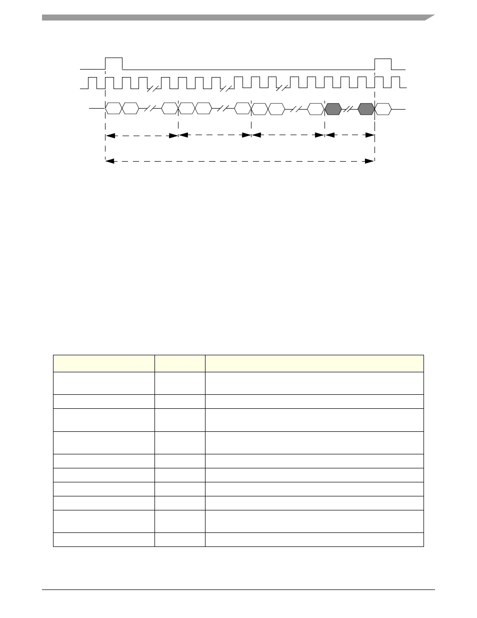
Figure 15-10. ESAI Data Transmission
shows an example how to configure the PSC1 as ESAI master. For the slave mode the bit
[GenClk] must be cleared and the
configuration of the
register can be ignored. In this configuration example the PSC will send 3 data words with 16 bit data in the 52
BitClk frame length. The last four bits in the frame will be empty (zero).
•
use PSC1 as ESAI master
•
16bit data, LSB first
•
BitClk frequency 4 MHz
•
FrameSync length 52 bit
•
data shifted out on the rising edge of BitClk
•
data transfer starts on FrameSync is active
•
FrameSync is active high
•
set the TFALARM level to 0x010, alarm occurs if 16 byte are in the TxFIFO
•
set the
level to 0x00C, alarm occurs if 12 byte space in the RxFIFO
•
enable TxRDY interrupt
Table 15-81. 16-bit ESAI Master Mode for PSC1
Register
Value
Setting
0x0A
Disable the Tx and Rx part for configuration if the PSC was enabled
by the work before.
0x12D20000
Select the 16bit Codec ESAI master mode, LSB first, DTS1=0
cdm_psc1_bitclk_config
0x8020
divide the
f
system
clock frequency from 528 to 16 MHz Mclk, see
Section 5.5.11, PSC1 Mclock Config Register—MBAR + 0x0228
cdm_clock_enable_register
0x00000020
enable Mclk, see
Section 5.5.6, CDM Clock Enable Register—MBAR +
0x33030000
set the FrameSync length (52 bit) and SCKL frequency
0x000C
set the RFALARM level to 0x00C
TFALARM
0x0010
set the TFALARM level to 0x010
0x0100
enable TxRDY interrupt
Port_Config
0x00000006
Select the Pin-Muxing for PSC1 Codec mode, see
0x05
Enable Tx and Rx
Frame length
start of Frame
Frame
CLK
DATA
first Data word
last Data word
empty Data
until the next
frame starts