J1850 vpw symbols -18 – Freescale Semiconductor MPC5200B User Manual
Page 697
MPC5200B Users Guide, Rev. 1
20-18
Freescale Semiconductor
Functional Description
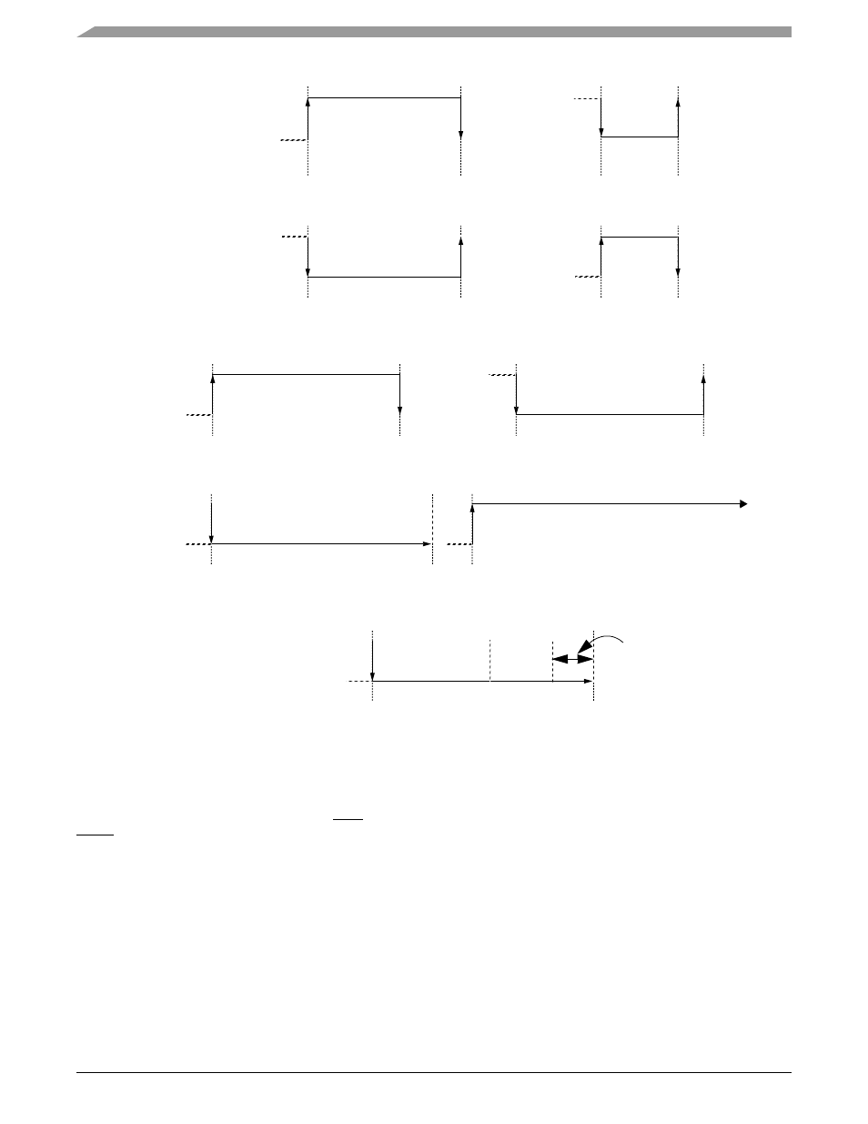
Figure 20-5. J1850 VPW Symbols
Each message will begin with an SOF symbol, an active symbol, and therefore each data byte (including the CRC byte) will begin with a
passive bit, regardless of whether it is a logic one or a logic zero. All VPW bit lengths stated in the following descriptions are typical values
at a 10.4kbps bit rate.
•
Logic “0”
A logic zero is defined as either an active to passive transition followed by a passive period 64
µs in length, or a passive to active
transition followed by an active period 128
(a)).
•
Logic “1”
A logic one is defined as either an active to passive transition followed by a passive period 128
µs in length, or a passive to active
transition followed by an active period 64
µs in length (
•
NB - Normalization Bit
The NB symbol has the same property as a logic “1” or a logic “0”.It is only used in IFR message responses. This bit is defined as
an active bit.
•
SOF - Start of Frame Symbol
128
µs
Active
Passive
64
µs
OR
Logic “0”
128
µs
Active
Passive
64
µs
OR
Logic “1”
200
µs
Active
Passive
Start of Frame
200
µs
End of Data
280
µs
Active
Passive
End of Frame
≥ 240µs
Break
(a)
(b)
(c)
(d)
(e)
(f)
300
µs
Active
Passive
Inter-Frame Seperator (IFS)
(g)
EOD
EOF
20
µs