Freescale Semiconductor MPC5200B User Manual
Page 146
CDM Registers
MPC5200B Users Guide, Rev. 1
Freescale Semiconductor
5-13
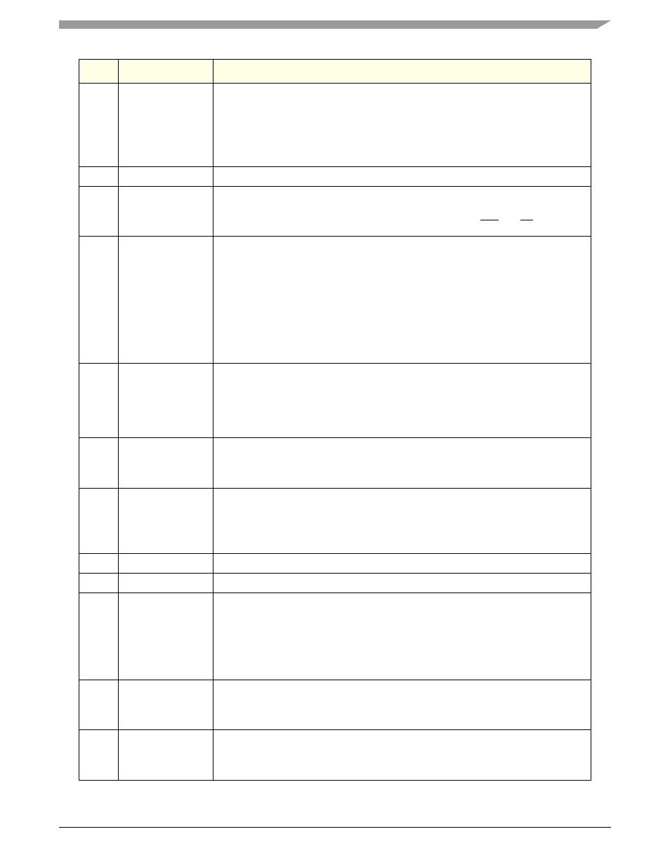
15
sys_pll_bypass
bit=0:Normal mode. The SYS OSC clock input is multiplied up by the system PLL, then
the PLL VCO is divided down to produce internal clocks.
bit=1:The SYS OSC clock input is used directly, bypassing the system PLL. No
multiplication of the input frequency is performed, but the input frequency is divided to
produce internal clocks just as the system PLL VCO frequency would be. sys_pll_cfg_1
and sys_pll_cfg_0 are ignored.
16
boot_rom_lf
Large Flash mode is selected
17
boot_rom_type
Latched pin value at reset.
bit=0:non-muxed boot ROM bus, single tenure transfer.
bit=1:muxed boot ROM bus, with address and data tenures, ALE and TS active.
18
boot_rom_size
Latched pin value at reset.
For non-muxed boot ROMs:
bit=0:8bit boot ROM data bus, 24bit max boot ROM address bus
bit=1:16bit boot ROM data bus, 16bit boot ROM address bus
For muxed boot ROMs:
boot ROM address is max 25 significant bits during address tenure.
bit=0:16bit ROM data bus
bit=1:32bit ROM data bus
19
boot_rom_swap
Latched pin value at reset.
bit=0:no byte lane swap, same
endian ROM image
bit=1:byte lane swap, different
endian ROM image
20
boot_rom_wait
Latched pin value at reset.
bit=0:4 PCI clocks of wait state
bit=1:48 PCI clocks of wait state
21
ppc_msrip
Latched pin value at reset.
microprocessor Boot Address/Exception table location.
bit=0:0000_0100 (hex)
bit=1:FFF0_0100 (hex)
22
—
Read Only. Do not write.
23
boot_rom_mg
Most/Graphic Mode is selected as BOOT mode
24
sys_pll_cfg_1
Latched pin value at reset.
bit=0:No operation.
bit=1:Internal System PLL frequency multiplication ratio specified by sys_pll_cfg_0 is
doubled (24x, 32x). No net effect on any internal clocks, except that PLL VCO runs
twice as fast. Useful in low frequency applications to keep VCO frequency (f
vcosys
)
above min, see MPC5200B Hardware Specification.
25
sys_pll_cfg_0
Latched pin value at reset.
bit=0: f
system
=16x SYS_XTAL_IN Frequency
bit=1: f
system
=12x SYS_XTAL_IN Frequency
26
xlb_clk_sel
Latched pin value at reset.
bit=0:XLB_CLK= f
system
/ 4
bit=1:XLB_CLK= f
system
/ 8
Bit
Name
Description