Simplified block diagram—mpc5200 -4 – Freescale Semiconductor MPC5200B User Manual
Page 38
Architecture
MPC5200B Users Guide, Rev. 1
Freescale Semiconductor
1-3
A dynamically managed external pin multiplexing scheme minimizes overall pin count. The result is low cost packaging and board assembly
costs.
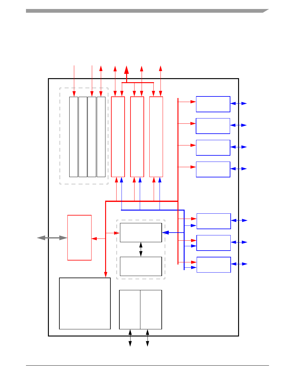
shows a simplified MPC5200B block diagram.
Figure 1-1. Simplified Block Diagram—MPC5200B
e
300 Co
re
SDRAM
/
DDR
JT
A
G
/ COP
In
terf
a
c
e
Reset / Cloc
k
MSCAN
Real-Time
Cloc
k
Sy
st
em Fu
nc
ti
o
n
s
Inte
rr
up
t C
o
ntro
ller
GPIO
/T
im
ers
PCI Bu
s C
ontroll
er
LocalPl
u
s
Controll
er
A
T
A Host
Cont
ro
lle
r
S
y
s
tem
s
In
terf
ac
e
U
n
it
(
S
IU
)
SDRAM /
DDR
Co
mmBus
Local
BestComm DMA
SRAM 16K
Bus
J1850
USB
SPI
I
2
C
Ethernet
PSC
Me
mo
ry
Controll
er
Generation
2x
2x
2x
6x